
Manual


-63-
The last experiment you did let you explore how
d
ata could be sent to two or more different outputs.
You can probably think of situations where we might
want to or need to do the opposite - which is
sending data from two different sources of output.
This circuit shows you how.
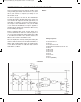
You see two different input sources when you view
the schematic. The multivibrator circuit provides one
of the input signals to LED 2; can you guess what
the other signal is provided by?
YOU! You provide the input signal by pressing and
relieving the key. The LED 1 is controlled by the
action of the key.
Before completing this project set the switch to A.
Once you have connected terminals 13 and 14 to
switch on the power LED 2 blinks. Keep your eye on
both LED 1 and LED 3. Has anything happened
yet? See what happens to LED 1 and LED 3 when
you press the key. At the same time as LED 1, LED
3 goes on and off. Set the switch to B. Now LED 3
turns on and off according to the blinking of LED 2.
To determine the output of LED 3, you can use
either of the two sources as the input.
Put on your thinking cap, and try following the inputs
from the multivibrator, to the key, to the setting of the
switch, to the LED. By each of the terminals of the
NANDs, mark either a 1 or 0 to observe the different
high and low inputs.
Computers use a more complex version of these
c
ircuits. As you probably guessed, the switching
from one input channel to another is usually done
electronically.
Notes:
EXPERIMENT #47: DATA SELECTOR USING TTL
Wiring Sequence:
o 13-49-42-45-131-137
o 14-119
o 73-50-31-138
o 86-82-74-72-80-62-33-36-39-121-133
o 71-57-34-44-114
o 37-61
o 40-113-85
o 41-116-79
o 51-53-54-132
o 43-115-81
o 52-59
o 55-56
o 58-60
o 13-14 (POWER)
Schematic
EP-130_62315RevC.qxp_EP-130_062812 6/23/15 11:17 AM Page 63