
Manual


-62-
It isn’t hard to think of some situations where we
might want to send input data to two or more
different outputs. This experiment shows how we
can use a network of NAND gates to help do that.
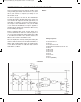
This circuit uses three NAND gates and a
multivibrator. Build the circuit, connecting terminals
13 and 14 last. If the switch is set to A then LEDs 1
and 2 will be blinking; if the switch is set to B then
LEDs 1 and 3 will be blinking.
Setting the switch to A or B controls the inputs to the
two NANDs that light LED 2 and LED 3 as shown in
the schematic. When the switch is A then the NAND
is controlling LED 2 gets one steady input of 1. The
other input is supplied by the output of the
multivibrator. As the multivibrator output switches
from 0 to 1, NAND controlling the LED 2 switches it
output from 1 to 0.
When you have the switch set to B, the opposite
happens. According to the input from the
multivibrator LED 3 can go on and off because the
NAND controlling the LED 3 gets a steady input of 1.
Notes:
EXPERIMENT #46: LINE SELECTOR USING TTL
Wiring Sequence:
o 13-49-34-37-42-45-131
o 14-119
o 71-57-54-31-44-114
o 86-82-80-72-59-60-62-33-121-133
o 36-55
o 39-58
o 40-113-85
o 41-116-79
o 43-115-81
o 50-51-53-132
o 52-56
o 13-14 (POWER)
Schematic
EP-130_62315RevC.qxp_EP-130_062812 6/23/15 11:17 AM Page 62