
Manual


-61-
Have you figured out how to make an enable circuit
using an OR gate? Well, if the answer is yes, then
t
his is your chance to compare you design to our
O
R enable circuit.
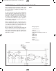
As done in projects 35 and 36, the multivibrator
provides the input to the OR gate in this circuit. You
can observe the output of the OR gate when you
view LED 1—it flashes on and off corresponding to
the output of the multivibrator. Can you tell what
occurs when the multivibrator’s input is applied to
the OR gate by viewing the schematic? Give it a try
before building the project.
Before completing this circuit, set the switch to A.
Connect terminals 13 and 14 to turn the power on
once you have finished the wiring. What does LED
1 do? What does LED 2 do? Set the switch to B.
What occurs to LED 1 and LED 2 now?
We can simplify the circuit by stating that setting the
switch to A blocks the flow of the data from LED 1 to
LED 2. We call this inhibit status. An enable status
occurs when the switch is at B; then data can flow
from LED 1 to LED 2.
Notes:
EXPERIMENT #45: “OR” ENABLE CIRCUIT USING TTL
Wiring Sequence:
o 13-49-42-45-131
o 14-119
o 71-50-51-31-44-114
o 86-82-80-72-59-60-62-33-36-121-133
o 34-58
o 40-113-85
o 41-116-79
o 43-115-81
o 52-56
o 53-54-132
o 55-57
o 13-14 (POWER)
Schematic
EP-130_62315RevC.qxp_EP-130_062812 6/23/15 11:17 AM Page 61