
Manual


-60-
Since we have made up some digital circuits by
combining NAND gates, it makes sense that we
m
ake XOR gates too. This circuit will show you how.
B
efore you complete this circuit set the switch to B.
Connect the terminals 13 and 14, once you have
finished the wiring. Does anything happen to LED 1
when you press the key? Release the key now and
set the switch to A. What occurs with the LED 1?
Now press the key while leaving the switch at A.
What happens with the LED 1 now?
As long as the inputs are different, output is 1. The
output of the XOR gate is 0, as long as both of the
inputs are the same - either 0 or 1.
Its thinking cap time again. Follow each 0 or 1 input
throughout the circuit until they reach the output. It
will help if you mark 0 or 1 on the input and the
output of each NAND gate on the schematic.
Notes:
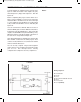
EXPERIMENT #44: “EXCLUSIVE OR” GATE USING TTL
Wiring Sequence:
o 13-49-131-137
o 14-119
o 31-61
o 72-62-33-133-121
o 71-50-53-138
o 57-51-132
o 54-52-56
o 55-59
o 58-60
o 13-14 (POWER)
Schematic
EP-130_62315RevC.qxp_EP-130_062812 6/23/15 11:17 AM Page 60