
Manual


-59-
I
f you are thinking that the NAND gate is a truly
versatile circuit, well then your right! This
experiment is a toggle flip-flop circuit made by using
f
our NAND gates.
When you have finished building this circuit,
connect terminals 13 and 14 in order to turn the
power on. Slowly press the key several times. You
will notice that each time the key is pressed the LED
1 turns on. Now it is time to put on your thinking cap
and try to trace what occurs from the key input to
LED 1. Two out of the four NANDs function as a R-
S flip-flop. See if you can figure out what the other
NANDs are doing.
This circuit is known as inverter because it takes the
inputs and reverses them.
N
otes:
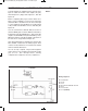
EXPERIMENT #43: “NAND” GATE MAKING A TOGGLE FLIP-FLOP
Wiring Sequence:
o 13-75-85-81-49-31-42
o 14-119
o 33-57-61-87
o 40-88
o 41-74-77
o 46-102-86
o 47-53-50-76
o 78-62-48-112-116-137-121
o 51-55-60
o 52-56
o 73-54-115
o 58-59
o 82-101-111-138
o 13-14 (POWER)
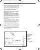
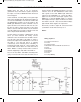
Schematic
EP-130_62315RevC.qxp_EP-130_062812 6/23/15 11:17 AM Page 59