
Manual


-57-
NAND gates are able to act as electronic
guardsmen. If you don’t want a signal to be placed
into input of a circuit, a NAND will make sure that it
doesn’t happen.
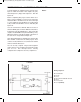
In the schematic, one thing that you recognize right
away is the multivibrator. By watching the LED you
can see the multivibrator. You will also realize that
the multivibrator provides one of the inputs to the
NAND gate. With the use of the schematic can you
figure out what occurs when the switch is set to A?
B? Are you able to figure out what occurs when
LEDs 1 and 2 do with the switch set to A and then
set to B? Make sure you that you make notes and
then compare them with what you learn.
Set the switch to B, before completing the circuit.
Once you have finished the wiring connect
terminals 13 and 14 and then look at LEDs 1 and 2.
You will notice that LED 1 will “blink” in order to
indicate the output of the multivibrator. Look now at
the LED 2. You will find that it is lighting
continuously, thus indicating that something is
preventing the LED signal at 1 from reaching the
second LED. Set the switch to A and then look at
LED 1. What is occurring? Is it the same occurrence
that was happening to both LED 1 and LED 2?
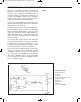
As you can see, LED 1 and LED 2 are taking turns
going on and off. This is because we make one of
the two inputs to the NAND equivalent to 1 once the
switch is set to A. The multivibrator sends 0 and
then signals to the other NAND input. When the
output for the multivibrator is 1, then the LED 1
lights but only because both input signals to the
NAND are 1, then the NAND output is 1 and the
LED 2 lights. Now try to figure out what occurs when
the switch is set to B – why does the LED 2 always
light. Hint: B switch supplies an output of 0.
Now were you able to figure all of that out before
you built the circuit? We sure hope so J
Notes:
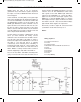
EXPERIMENT #41: “NAND” ENABLE CIRCUIT USING TTL
Wiring Sequence:
o 13-49-53-54-42-45-131
o 14-119
o 71-50-31-44-114
o 86-82-80-72-56-57-59-60-62-33-36-121-133
o 34-52
o 40-113-85
o 41-116-79
o 43-115-81
o 51-132
o 13-14 (POWER)
Schematic
EP-130_62315RevC.qxp_EP-130_062812 6/23/15 11:17 AM Page 57