
Manual


-56-
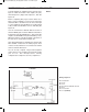
Setting the switch to B blocks the channel from the
LED 1 to the LED 2 However, when you set the
switch to A, you will find that LED lights and turns off
at the same time as LED 1. The two NAND gates
produce an AND gate.
In this circuit the LED 1 is known as the data input.
The output is the LED 2. Frequently these terms are
used with enable circuits. They will show up from
time to time when we talk about digital circuitry.
As you may have suspected by now, we can use
digital circuits to perform enable functions. Are you
able to figure out how? Make sure to keep the notes
of your findings especially if you are able to figure
out how to use an OR gate in an enable circuit.
Notes:
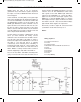
EXPERIMENT #40: “AND” ENABLE CIRCUIT USING TTL
Wiring Sequence:
o 13-49-42-45-131
o 14-119
o 71-50-31-44-114
o 86-82-80-72-56-57-59-60-62-33-36-121-133
o 34-55
o 40-113-85
o 41-116-79
o 43-115-81
o 51-132
o 52-53-54
o 13-14 (POWER)
Schematic
EP-130_62315RevC.qxp_EP-130_062812 6/23/15 11:17 AM Page 56