
Manual


-52-
B
y using your kit’s NAND gates, are you able to
figure out how to make an AND gate? To find out
let’s experiment!
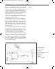
As you build this circuit, leave the switch at B.
connect terminals 13 and 14 to turn the power on
once you have finished. Now press the key. What
happens to LED 1? Now while pressing the key, set
the switch to A. Are there any changes in LED 1?
As you can observe by setting the switch to A and
then pressing the key, makes the inputs 1, causing
the overall output to be 1. Are you able to flow the 1
input through the circuit until you reach a 1 output?
Give it a try, but don’t peek at the answer.
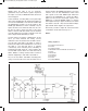
Here is how it works – each 1 input goes into the
first NAND gate. Thus causing the output of the
NAND to be 0. This 0 output is used for both inputs
to the second NAND. The LED lights when the 0
inputs to the second NAND cause its output to be 1.
AND gate is formed from two NAND gates.
N
otes:
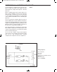
EXPERIMENT #36: “AND” GATE USING TTL
Wiring Sequence:
o 13-49-131-137
o 14-119
o 31-55
o 72-56-57-59-60-62-33-133-121
o 50-71-138
o 51-132
o 52-53-54
o 13-14 (POWER)
Schematic
EP-130_62315RevC.qxp_EP-130_062812 6/23/15 11:17 AM Page 52