
Manual


-50-
H
ave you ever wondered what happens once you
start adding digital circuits together, using the output
of one as the input of another? You’ll find out when
you build this project.
A quad two-input NAND gate IC, is one of the
integrated circuits contained in your kit. Some of
these words will probably be a confusing at first. IC
is short for integrated circuit. Something that
contains many transistors, diodes, and resistors in
one small package is an integrated circuit. This
NAND gate uses TTL, short for Transistor-
Transistor-Logic, because it is mostly constructed
using transistors.
Quad means four. There are four separate NAND
gate circuits, in this IC each receiving two inputs.
Two input terminals are for Each NAND gate.
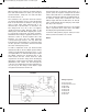
As you build this project make sure to consult to the
schematic. This circuit takes the output from one
NAND gate, and uses it for both inputs to the
second (both inputs for the two NANDs are always
the same here). What do you think happens if the
input to the first NAND is 1, after learning about
NANDs? If the first input is 0? Attempt to figure it out
before building this project.
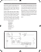
Set the switch to B before completing the wiring. To
turn the power on, connect terminals 13 and 14.
What happens to LED 1? Set the switch to A. LED
1 lights up.
1
is the input when the switch is set to A, and 0 is
the input when the switch is at B. When the input to
the first NAND is 1, its output is 0. But the 0 output
of the first NAND is the input to the second. The 0
input to the second makes its output become 1,
lighting the LED.
Notes:
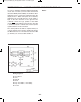
EXPERIMENT #34: “BUFFER” GATE USING TTL
Wiring Sequence:
o 13-49-131
o 14-119
o 31-55
o 33-56-57-59-60-62-133-121
o 50-51-132
o 52-53-54
o 13-14 (POWER)
Schematic
EP-130_62315RevC.qxp_EP-130_062812 6/23/15 11:17 AM Page 50