
Manual


-47-
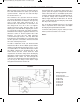
It is easy to determine what the NOR (inverted OR)
circuit does now that you have built and learned
a
bout the NAND (inverted AND) circuit. When either
t
erminal A or B is connected to terminal H (119) the
display shows L. When low inputs are received by
terminals both A and B then the circuit output is
high. In the OR circuit this is the opposite. The
schematic shows the logic symbol for the NOR
circuit. A + B is the writing for the function. The OR
is symbolized by the + and the bar over the symbol
signifies that the circuit is inverted.
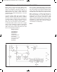
The current path for the LED is complete when you
connect either A or B (or both) to terminal H, turning
the NPN transistor on. The transistor and the LED
go off when you connect both A and B to L.
Notes:
EXPERIMENT #32: “NOR” TRANSISTOR CIRCUIT WITH DISPLAY
Wiring Sequence:
o 18-19-20-119
o 25-47
o 46-82-84
o 48-124
o 81-(to 119 “HIGH” or 124 “LOW”)
o 83-(to 119 “HIGH” or 124 “LOW”)
o 121-122
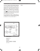
Schematic
EP-130_62315RevC.qxp_EP-130_062812 6/23/15 11:17 AM Page 47