
Manual


-43-
Now it is time to step into the world of digital circuits
and learn some basics. A circuit that acts as a
s
witch to turn different components off and on is a
d
igital circuit. In this section you will be dealing with
diode-transistor logic (DTL) circuits- these are
circuits that use diodes and transistors to turn the
power on and off.
It doesn’t usually matter how much voltage is
applied to a digital circuit; what matters is whether
the circuit is off (no voltage present) or on (presence
of voltage). When a circuit is off we describe it as
logic low or use the number 0. When a circuit is
turned on we say logic high or use the number 1.
A switch that turns circuits on and off is a toggle
switch. In this experiment we will use the flip-flop
circuit to work as a toggle switch. In this project,
unlike others that you will be doing later, the circuit
does not change until you tell it to.
Once you have completed the wiring, set the switch
to A. The lower part of the LED lights up. Press the
k
ey now. The upper section lights up while the lower
s
ection shuts down. Every time you press the key
the LED sections will change, thus a flip and a flop.
When a transistor is on and the other transistor is
off, it will stay either on or off until you tell it to
change. We can easily say that a flip-flop circuit
remembers. Once you put a circuit into a certain
setting, it will stay that way until you tell it to change.
Controlled by a single toggle signal, flip-flops can
remember many things. This is also why computers
can remember so many things.
Notes:
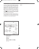
EXPERIMENT #28: “TOGGLE FLIP-FLOP” TRANSISTOR
Wiring Sequence:
o 84-108-44-17
o 81-106-41-20
o 25-124-137
o 40-107-83
o 42-45-130 -110-72
o 43-105-82
o 71-75-111-131-129
o 76-109-112-138
o 119-132
o 121-122
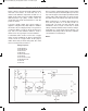
Schematic
EP-130_62315RevC.qxp_EP-130_062812 6/23/15 11:17 AM Page 43