
Manual


-42-
W
hat is a flip-flop? It is a kind of circuit that changes
back and forth between two states (on and off) at
specific intervals. It flips into one state and flops
i
nto another and so on.
Two transistors, two capacitors and four resistors
are used by the flip-flop to turn on and off the LED.
Each of the transistors are always in the opposing
state of each other; when transistor Q1 is on,
transistor Q2 is off; when Q2 is on then Q1 is off.
The change from on to off or off to on, happens
quickly (in microseconds). Note the effect on the
flashing rate of the LED when adjusting the control.
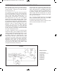
To see how this circuit works, look at the schematic.
Remember when voltage is applied to the base of a
transistor, it turns on. On the negative side of the
batteries you have the two PNP transistor
connected through resistors. You may think that
both transistors would always be on however, there
are two capacitors connected to the bases that aid
the cause of the flip-flop action.
In order to explain the circuit, you should assume
that transistor Q1 is off. The 100mF capacitor will be
charging and discharging through its base, so we
can say that Q2 is on. Transistor Q2 is kept on after
the 100mF capacitor has discharged due to the
47kW resistor and the control. Now the 10mF
capacitor has received a charge and is discharging
through the 4.7kW resistor, the battery and the Q2.
(Remember that current can flow through the
collector to the emitter when transistor Q2 when it is
on.) As long as the charge on the 10mF is high
enough the Q1 transistor remains off.
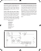
T
ransistor Q1 turns on when the charge drops to a
specific point, the negative voltage from the 47kW
r
esistor. Once Q1 turns on, and 100mF quickly starts
charging and transistor Q2 turns off. With the Q2 off,
its collector voltage rises toward the 9V of the
battery supply and thus the LED turns off. The Q1
turns on fully through the fast charging of the 10mF.
This flip occurs very fast.
The circuit will eventually flop back to the original
state to repeat the above action due to the 100mF
discharging through the Q2 transformer.
Look back at the previous projects and try to locate
where you have used this sort of circuit.
Notes:
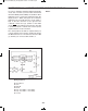
EXPERIMENT #27: “FLIP-FLOP” TRANSISTOR CIRCUIT
Schematic
Wiring Sequence:
o 21-23-41-114
o 75-81-87-25-27-124
o 28-79-82
o 40-115-80
o 45-42-119
o 43-88-113
o 44-116-76
o 121-122
EP-130_62315RevC.qxp_EP-130_062812 6/23/15 11:17 AM Page 42