
Manual


-40-
T
his project shows how to control the LED display
through the use of transistors.
This circuit is similar to the one in Project 18
(Transistor Action). The differences between these
two are the position of the switch as well as the
value of the resistor. In this project we use the base
circuit of the NPN transistor as a switch, in order to
control the cathode of the LED. Project 18
controlled the LED from the anode (positive side).
The transistors in this circuit act as switches. The
PNP transistor is always on, allowing the current to
flow from the collector to the emitter, because a
sufficient amount of the negative voltage is applied
to its base through one of the 10kW resistors. When
you press the key the NPN transistor turns on,
thereby applying sufficient positive voltage to its
base, through the use of another 10kW resistor.
When you close the key, then current can flow from
the PNP’s emitter to its collector.
Here are some important basic principles for you to
remember:
• When negative voltage is applied to its base, a
PNP transistor turns on; the current flows from
the collector to the emitter.
• When positive voltage is applied to its base, a
NPN transistor turns on; the current flows from
the emitter to the collector.
Current can now flow through the NPN transistor,
thus current can now travel a complete path - from
the negative batteries side, to the NPN transistor, to
the common cathode terminal of the display, to the
PNP transistor, to the positive side of the batteries –
thus lighting the display.
Turning on the LED with either of the transistors
may not see important to you now. But, to people
who design computer circuits that are complicated,
it is an easy way to control the circuits.
Have you noticed that transistors switch on and off
as fast as you press the key? These quick switching
allows operations to be performed quickly by
computers. Transistors are many times faster than
hand operated switches or relays. Later you will see
how to delay this fast switching by using other
components.
N
otes:
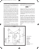
EXPERIMENT #26: SWITCHING THE LED DISPLAY USING TRANSISTOR CONTROL
Wiring Sequence:
o 21-23-41
o 25-47
o 40-82
o 119-42-137
o 46-84
o 124-48-81
o 83-138
o 121-122
Schematic
EP-130_62315RevC.qxp_EP-130_062812 6/23/15 11:17 AM Page 40