
Manual


-39-
I
n this project you will see how to turn on an LED by
using a transistor and a CdS cell.
Think of the CdS cell as a resistor that changes its
r
esistance based upon the amount of light that falls
upon it. In the dark the resistance is very high,
around 5 megohms (MW, 5 million ohms); in bright
sunlight, it can decrease to about 100W or less.
To test this easily; just set your VOM to the
resistance function and then connect it to the CdS
cell. Now hold you hand over the CdS cell and note
its resistance. Read the resistance again once you
have moved your hand.
For a switch you can use the NPN transistor. This
transistor turns on when sufficient positive voltage is
applied to its base. Positive voltage leads from the
positive terminal of the battery, then to the CdS cell,
to the control, and then finally to the 10kW resistor.
The amount of voltage applied to the transistor’s
base is determined by the total resistance value of
the CdS, the control, and the 10kW resistor. The
amount of light striking the cell and the control
setting change the base voltage - making it either
high or low enough to turn on the transistor. Using
your voltmeter on the control, try to change the
control position while casting a shadow over the
CdS to verify the voltage change. When light
changes over the CdS, adjust the control so that the
transistor turns on and off.
Under bright light the circuit displays a 1. You can
connect the wires to display any number you desire.
1 might be considered to be a binary digit, showing
logic “high” (H or ON), as indication of the presence
of a bright light on the CdS cell. Can you rewire this
circuit to display another character to indicate this
condition?
N
otes:
EXPERIMENT #25: LED DISPLAY WITH CdS AND TRANSISTOR
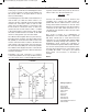
Wiring Sequence:
o 15-21-23-119
o 16-28
o 25-47
o 124-26-48
o 27-82
o 46-81
o 121-122
Schematic
EP-130_62315RevC.qxp_EP-130_062812 6/23/15 11:17 AM Page 39