
Manual


-38-
W
ire the circuit as shown to connect the 3V supply
to the LED segments and the decimal point (Dp).
What numbers and letters do you see displayed?
I
n this experiment you can make some voltage
measurements using a Voltage/Ohm Meter (VOM) if
you have one. Connect the VOM as directed by its
instructions. Skip these measurements if you do not
have a VOM.
With this low battery voltage, you can reverse the
polarity of the circuit by reversing the connections to
the battery. (Changes to make are: change 25-120
and 119-WIRE, 25-119 and 120-WIRE.) Record
your results. After you note your results, reconnect
the battery with the correct polarity. Measure the
LED voltages between terminal 25 and each
separate terminal (17 through 24) using a VOM if
you have one. Change the battery connections to
25-124, 121-122, and 119-WIRE to temporarily
change the 9V supply. Next, make the same
measurements. What amount is the LED voltage
increased by, from using this three-time increase
from the battery? (A normal increase is 0.25V)
Next, try measuring the voltage in each resistor
attached to one of the LED segments. All of the
resistors are 360W. The LED current is in milliamps
(one-thousandths of an ampere) is calculated by
dividing the voltage by 360W. The LED segment
currents are approximately ____ milliamperes (mA)
with the 3V supply (3mA typically), and ____ mA
with the 9V supply.
Make a chart of the connections required to display
0 through 9 on the display in the space below.
N
otes:
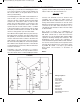
EXPERIMENT #24: DIGITAL DISPLAY CIRCUIT FOR THE SEVEN-SEGMENT LED
Wiring Sequence:
o 25-120
o 119-WIRE
or
o 25-120
o 119-(17, 18, 19, 20, 21, 22, or 23)
Schematic
EP-130_62315RevC.qxp_EP-130_062812 6/23/15 11:17 AM Page 38