
Manual


-35-
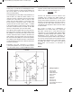
A two-transistor amplifier is used in this circuit. In an
amplifier, a small signal is used to produce or
control a large signal. This circuit is similar to an
early model transistor hearing aid amplifier.
Your kit’s speaker can change sound pressure into
a weak voltage. The transformer increases the
voltage, and which is then applied to the NPN
transistor through the 3.3mF capacitor.
Now it is time to talk about the transformer. The
transformer has a copper wire wound hundred of
turns. We call this a coil. A transformer has two coils
separated by an iron plate.
A magnetic field is created when electricity flows
through a coil. The reverse is also true - if a coil is
subjected to a change in its magnetic field strength,
electricity flows through it. The magnetic field
created depends on the number of windings in the
coil, so when electricity flows through the first coil
(the primary coil), the voltage at the second coil (the
secondary coil) will be different if the number of
windings is different. Induction is the creation of an
electric charge using a magnetic field. Now go back
to project 17 and think of how a large voltage is
induced at the secondary side when 9V is applied to
the primary side of the transformer.
Notes:
EXPERIMENT #22: AMPLIFY THE SOUND
Wiring Sequence:
o 1-29
o 2-30
o 3-112
o 5-124-48-116-102-78-13-EARPHONE
o 93-109-40
o 41-94-77-14-EARPHONE
o 42-72
o 91-100-101-111-46
o 75-92-99-110-47
o 71-76-115-119
o 121-122
Schematic
EP-130_62315RevC.qxp_EP-130_062812 6/23/15 11:17 AM Page 35