
Manual


-34-
In this project, you will discover what happens when
you connect resistors in series and in parallel. You
w
ill see the LED-1 on the panel flash on and off
when you finish wiring.
See what happens to the LED on side A and then on
side B when you slide the switch. There is no
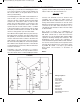
change at all. The schematic shows that two 10kW
resistors are connected in series to side A of the
switch, and one 22kW resistor is connected to side
B. The resistors connected in series on side A are
equal to the sum of each resistor’s value – so 20kW
is the total resistance of the resistors. This is about
the same as 22kW resistance in side B. So the LED
shows no change when you move the switch.
The LED becomes brighter when you press the key.
By looking at the schematic, you will see that resistor
R1 (470kW) is connected to the LED in series. The
resistor controls the flow of current to the LED. The
total resistance decreases when you press the key,
R1 and resistor R2 (100W) are connected in parallel.
The LED becomes brighter because of the amount
of current flowing to it increases, when the amount of
resistance decreases.
Calculating the total resistance for resistors
connected in parallel is not as easy as when resistors
are connected in series. You must multiply the values
together, and then divide the product by the sum of
values. In this case, the total resistance is:
Connect now terminals 13-14. As shown in the
schematic, this connects the 22kW resistor in
parallel with the two 10kW resistors. Is there any
change in the LED? The flashes on and off of the
LED are at shorter intervals because the resistance
connected to the slide switch decreases. Try to
calculate the new resistance value. The new value
is about 10.5kW.
This circuit is known as a multivibrator. A
multivibrator is an oscillator that uses components
that direct current back to each other. From the
schematic you can see that the 10mF and the 100mF
capacitors discharge through the transistors. This
multivibrator circuit controls the oscillations to
create the flash through the LED at certain intervals.
You can now see that resistors and capacitors have
opposite effects when they are connected in series
or parallel. Be careful - it is easy to get confused
about which one increases or decreases in
strength.
Notes:
EXPERIMENT #21: SERIES AND PARALLEL RESISTORS
Wiring Sequence:
o 31-41-114
o 79-116-44
o 40-115-85-81
o 43-113-87
o 32-71
o 72-138
o 82-84
o 13-83-131
o 14-86-133
o 33-80-88-137-132-121
o 45-42-119
Schematic
470 x 100
(470 + 100)
= 82W
EP-130_62315RevC.qxp_EP-130_062812 6/23/15 11:17 AM Page 34