
Manual


-33-
In this experiment you study the switching action of
transistors in turning an LED on. You will be using
two different transistors - one of the two PNP types
and the NPN type included in your kit. PNP and the
NPN refers to the arrangement of the
semiconductor materials inside the transistors.
The NPN transistor at the bottom of the schematic
stays on due to the 47kW resistor supplying voltage
to its base. Making the connection through the
22kW resistor causes the PNP transistor at the top
of the schematic to turn on.
The resistance of the 22kW is approximately half of
that of the 47kW resistor, so the current supplied to
the base of the PNP transistor is about twice that of
the NPN. Therefore the PNP is turned on “greater”
than the NPN.
Connect the circuit and then press the key: 1 is
displayed. To increase the base current for the NPN
transistor, you have to decrease the value of the
47kW resistor connected to the base – terminal 46.
To do this simply disconnect between 87 and 88 and
then replace them with connections to another
resistor. For example, change connection 87-42 to
83-42 and connection 46-88 to 84-46, to change the
47kW to a 10kW resistor. Every time that you lower
the resistor value more current is then supplied to
the base of the transistor, and the LED display lights
a little brighter when you press the key. If you
decrease the resistance below 1kW the transistor
may burn out.
Next, change the resistors to 10kW and then press
the key. Use terminals 83 and 84 and terminals 81
and 82. With the transistors both fully on the
brightness should not change much. If change does
occur check your batteries.
Notes:
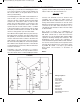
EXPERIMENT #20: TRANSISTOR SWITCHING
Wiring Sequence:
o 21-23-41
o 25-47
o 40-85
o 87-42-119
o 46-88
o 124-48-137
o 86-138
o 121-122
Schematic
EP-130_62315RevC.qxp_EP-130_062812 6/23/15 11:17 AM Page 33