
Manual


-32-
S
ome of the handiest items in your kit are the
capacitors. They store electricity, smooth out
pulsing electricity into a steady flow and let some
electric current flow while blocking other current.
This circuit allows you to compare the effects of
capacitors connected in both series and parallel.
Once you have finished wiring this project, set the
switch to B. Next connect terminals 13 and 14. You
will hear a sound coming from the speaker. In this
case, electricity is flowing through the 0.01mF
capacitor (refer to the schematic to help understand
this). Press the key now. What happens?
You will hear a lower-pitched sound coming from the
speaker, because the 0.05mF capacitor has been
added in parallel to the first capacitor. Current now
flows through both capacitors at the same time,
through two channels that are separate. What do
you think happens to the total capacitance when
you connect two capacitors in parallel?
You may have guessed wrong. When connected in
parallel, two capacitors make the total capacitance
increase. The tone is lower because the increased
capacitance causes it to be.
Now release the key and then move the switch from
B to A. While the switch is set to A, do not press the
key. Now what do you hear?
You now hear a high-pitched sound coming from the
speaker. This is due to the 0.05mF and 0.01mF
capacitors are now connected in series – the flow of
the current goes directly from one to the other. The
total of the capacitance in the circuit is less than the
s
mallest capacitor in the series connection. The
higher-pitch sound is caused by the lower
capacitance.
Notes:
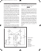
EXPERIMENT #19: SERIES AND PARALLEL CAPACITORS
Wiring Sequence:
o 1-29
o 2-30
o 3-91-110-132
o 4-121
o 5-41-109
o 13-42
o 14-119
o 40-92-101-137
o 102-106-133
o 105-131-138
o 13-14 (POWER)
Schematic
EP-130_62315RevC.qxp_EP-130_062812 6/23/15 11:17 AM Page 32