
Manual


-31-
T
here are three connections made on a transistor;
one of these (the base) controls the current
between the other two connections. The important
r
ule to remember for transistors is: a transistor is
turned on when a certain voltage is applied to the
base. A positive voltage turns on an NPN type
transistor. A negative voltage turns on a PNP type
transistor.
In this project the LED display shows which
transistor is on by lighting either the top or the
bottom half. This demonstrates how a positive
voltage controls an NPN transistor and the PNP
transistor is controlled by a negative voltage.
After the connections are made the NPN transistor
will be turned on because the positive voltage
through the 1kW resistor is applied to the base. This
turns on the upper half of the LED display.
Simultaneously the PNP is off because current
cannot flow to its base. (The current flows from the
PNP emitter to the NPN transistor base; however,
this flow from the PNP base is blocked by the
diode.)
The NPN is turned off if you press the key, because
current is diverted away from its base. The PNP is
turned on simultaneously because now current can
flow from its base through the 4.7kW resistor. As a
result, the upper LED segments turn off and the
lower segments turn on.
N
otes:
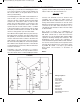
EXPERIMENT #18: TRANSISTOR ACTION
Wiring Sequence:
o 18-17-21-48
o 19-20-23-41
o 25-124-138
o 40-80-77
o 75-78-47-42-119
o 76-46-126
o 79-137-125
o 121-122
Schematic
EP-130_62315RevC.qxp_EP-130_062812 6/23/15 11:17 AM Page 31