
Manual


-30-
I
n this circuit single pulses of high voltage electric
energy are generated by suddenly discharging a
charged capacitor through a transformer.
Automobile ignition systems use a similar capacitor-
discharge reaction.
The operation of this circuit is simple but the
concepts involved are important to helping you
understand more complicated circuits. If you have
access to an oscilloscope, you can scientifically
measure the energy that is discharged through the
transformer.
The 470mF capacitor stores up energy as the
batteries supply millions of electrons to the
capacitors negative electrode. Meanwhile the
batteries draw the same number of electrons from
the capacitors positive electrode so that the positive
electrode is lacking electrons. The current must
pass through the 4.7kW resistor, so it requires at
least 12 seconds for the capacitor to receive the full
9V charge from the batteries.
The amount of charge a capacitor can store
depends on its capacitance value and the voltage
applied across it. This represents the amount of
electrons displaced in the electrode.
The amount of electrons in a capacitor’s electrode is
measured in coulombs. The quantity of one
coulomb is 6,280,000,000,000,000,000 electrons
(6.25 x 10
18
).
The charge in either electrode of the capacitor is
determined by multiplying the capacitance (C) by
the voltage across the capacitor (E). (Q = C x E).
The 470μF (470 x 10
-6
F) capacitor at 9V is
calculated as follows:
Q = C x E = 470 x 10
-6
x 9 = 4.23 x 10
-3
coulombs
or:
470 x 0.000001 x 9 = 4.23 x 10
-3
coulombs
(265,564,400,000,000 electrons)
Pressing the key causes the above number of
electrons to pass through the transformer winding in
a very short time and induces a high voltage in the
secondary winding. Thus causing the LED to flash.
An oscilloscope is an electronics measurement
instrument used by engineers and technicians. If
you have access to one, connect it (with help from
someone who knows how to use it) to terminal 3
and terminal 5 of the transformer to indicate the
presence of 90V or more. The indicated voltage is
p
roduced when the charge held by the capacitor is
released into the transformer.
Notes:
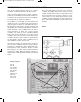
EXPERIMENT #17: CAPACITOR DISCHARGE FLASH
Wiring Sequence:
o 1-138
o 2-118-124
o 3-31
o 5-33
o 79-119
o 80-117-137
o 121-122
Schematic
EP-130_62315RevC.qxp_EP-130_062812 6/23/15 11:17 AM Page 30