
Manual


-29-
H
ow about we take a break? This circuit is for
entertainment. The numbers 1 and 2 will flash on
the display in the circuit. This might remind you of
s
ome neon signs that have eye-catching
advertisements on them.
A “flip-flop” circuit controls the LED display in this
experiment. In later projects you will be learning
more about flip-flop circuits. Try a different value for
the capacitors to see the effects on the operation
speed. Try and rewire the LED display to flash
numbers other than 1 and 2. Try placing higher
values in place of the 22kW and 4.7kW resistors. Do
not use lower values for any of the resistors or else
you could damage the transistors.
N
otes:
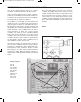
EXPERIMENT #16: FLIP FLOPPING
Wiring Sequence:
o 17-19-20-22-41-116-82
o 21-42-45-119
o 23-44-118-84
o 79-81-83-85-25-124
o 80-117-40
o 86-115-43
o 121-122
Schematic
EP-130_62315RevC.qxp_EP-130_062812 6/23/15 11:17 AM Page 29