
Manual


-152-
T
he twin-T type audio oscillator is very popular for
use with electronic organs and electronic test
e
quipment because it is very stable.
The resistors and capacitors in the twin-T network
determine the frequency of oscillation. The letter T is
used because the resistors and capacitors are
arranged in the shape of the letter T in the schematic
diagram. There are two T networks in parallel
across from each other; hence the term twin is used.
The capacitors in series shift the phase of the wave;
the resistors in series supply voltage to the
transistor’s base as well as shifting the phase of the
wave.
Carefully adjust the circuit to obtain pure sine wave
output as in the previous two projects. Modify the
control very slowly over its entire range until you
hear a tone in the earphone that is very low and
resembles the lowest note of a large pipe organ.
This control setting should be between 7 and 10 on
your dial.
Once the oscillation has started, adjust the control
carefully for the setting that gives the purest
sounding low note near the high end of the dial.
You can experiment with this circuit in many ways.
We suggest you try different values for the 10kW and
470W resistors, and try using higher and lower
battery voltages. Also, if you have a VOM, try
measuring circuit voltages.
N
otes:
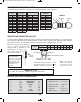
EXPERIMENT #130 TWIN-T OSCILLATOR
Schematic
Wiring Sequence:
o 72-106-116-27-124
o 28-104-102
o 46-103-87
o 47-101-86-81-89
o 90-EARPHONE
o 48-71
o 119-115-82-EARPHONE
o 85-88-105
o 121-122
EP-130_62315RevC.qxp_EP-130_062812 6/23/15 11:18 AM Page 152