
Manual


-151-
I
n this experiment, you build and study a low-
distortion sine wave oscillator. Build this experiment
after you have built and studied the previous
e
xperiment because this one has no transformer;
transformers are likely to cause distortion because of
their non-linear characteristics.
As in the previous experiment, you should listen to
the tone of this oscillator and modify the control for
the clearest-sounding single tone (the one with the
least distortion). Again, start with the control near
maximum. The operating frequency is about 300Hz
at the minimum distortion setting of the control.
We call this circuit an RC phase shift oscillator, and it
is considered a basic sine wave oscillator. The
positive feedback of the signal causes oscillations to
occur. The resistors (R) and capacitors (C) make up
the path for the signal to the transistor base. Every
time the signals pass the RC circuits, a slight time lag
occurs. In other words, the rise and fall of the wave
(the phase) shifts slightly. That’s why we call it phase
shift. After the signal has traveled through the circuit,
the phase shifts 180 degrees. When the collector
voltage rises, this rise is fed back to the collector with
the phase shifted. When the base voltage rises, the
collector voltage falls. This repeating cycle causes
the transistor to oscillate.
The frequency changes when you change the control
setting, because the degrees of phase shift changes.
The tonal quality also changes. Set the control to the
point where you can hear the purest tone; at this
point a clear sine wave is generated.
N
otes:
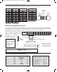
EXPERIMENT #129: SINE WAVE OSCILLATOR WITH LOW DISTORTION
Wiring Sequence:
o
124-27-48-82-80-EARPHONE
o
47-105-93-77-87
o
88-EARPHONE
o
81-109-108-28
o
94-110-46
o
78-138
o
79-106-107
o
119-137
o
121-122
Schematic
EP-130_62315RevC.qxp_EP-130_062812 6/23/15 11:18 AM Page 151