
Manual


-148-
I
f you use a meter you can find the exact value of a
resistance; but when you only want to know
a
pproximate resistance values, you can use this
resistance tester.
This circuit converts resistance to electric current
and compares it with the comparator’s reference
current to tell you the approximate range of
resistance. The comparator has a reference voltage
of about 0.82V.
Build the circuit and set the switch to position A.
Connect the material to be tested between
terminals 13 and 14. The LED lights if the resistance
is less than 100kW, otherwise it is off. If the LED
lights, connect terminals 93 and 86. If the LED turns
off now the resistance is between 10W and 100kW.
If it stays on, remove the wire from terminal 86 and
connect it to terminal 84. If the LED turns off now,
the resistance is in the range of 1 to 10kW. If the
LED still doesn’t turn off, remove the wire from
terminal 84 and connect it to terminal 76. If the LED
turns off now, it means that the resistance is in the
range of 100W to 1kW; if it stays on, the resistance
is less than 100W.
N
otes:
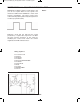
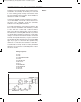
EXPERIMENT #126: RESISTANCE TESTER
Schematic
Wiring Sequence:
o 13-93-69-WIRE
o 14-79-70-121
o 75-83-94-90-88-31-63-131
o 33-67
o 68-80-87
o 85-89
o 119-124
o 122-132
EP-130_62315RevC.qxp_EP-130_062812 6/23/15 11:18 AM Page 148