
Manual


-142-
W
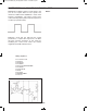
hen you connect the signal from this oscillator to
an oscilloscope, it creates a pattern that looks like
the teeth of a saw (as shown below).
The shape of this wave results from the slow
charging of the 0.1mF capacitor through the control
and the 100kW resistor, and the capacitor’s
discharge through the PNP and NPN transistors.
The voltage divider - the 470W and 100W resistors -
provides about 1.6 volts to the transistors. Current
flowing from the 9V supply into the 0.1mF capacitor
(through the control and the 100kW resistor) slowly
charges up the capacitor. When the capacitor’s
charge exceeds the voltage of the voltage divider
(1.6V), the transistors turn on and provide a path for
the 0.1mF capacitor to discharge quickly. Now, the
transistors turn off again, and the capacitor begins
to slowly charge to repeat the cycle.
You can modify the oscillator frequency by changing
the values of the components in the timer circuit -
the control, the 100kW resistor and the 0.1mF
capacitor. Try a 47kW resistor or a 220kW resistor in
place of the 100kW resistor, and try several different
capacitors. If you connect one of the electrolytic
capacitors, be sure that you use the proper polarity
(+ and –).
N
otes:
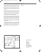
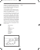
EXPERIMENT #120: SAWTOOTH OSCILLATOR
Schematic
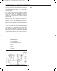
Wiring Sequence:
o 73-81-27-119
o 28-89
o 71-74-47-40
o 41-46
o 42-43-90-109
o 124-44-48-110-72-EARPHONE
o 45-82-87
o 88-EARPHONE
o 121-122
EP-130_62315RevC.qxp_EP-130_062812 6/23/15 11:18 AM Page 142