
Manual


-137-
T
his experiment uses the LED and an audio
oscillator alarm to indicate three different levels of
w
ater in a container. The water is used as a
conductor to complete the circuits and show the
water level.
When the water is below all three of the wire
connections, only the bottom segment (D) of the
LED is on (indicating a low water level).
When the water is at a level that touches the two
long wires connected to terminals 77 and 124 (but is
below the shorter wire), the base current turns on
transistor Q2 and the middle segment of the LED (G)
turns on (indicating a moderate water level).
If the water rises to a level high enough to touch all
three wires, the base current is supplied to transistor
Q1, and the top segment of the LED (A) lights. The
audio oscillator is also activated as a warning of a
high water level.
Of course, you can alter this wiring to make the LED
display show other letters of symbols to indicate the
different water levels. Can you think of any other
symbols? (How about L = low, C = center, and H =
high?)
N
otes:
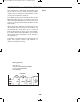
EXPERIMENT #115: WATER LEVEL WARNING
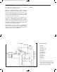
Wiring Sequence:
o 1-29
o 2-30
o 3-103-109
o 4-17-41-87
o 5-47-110
o 20-42-45-119
o 22-44
o 25-48-124-WIRE
o 40-76
o 43-78
o 46-104-88
o 75-WIRE
o 77-WIRE
o 121-122
Schematic
EP-130_62315RevC.qxp_EP-130_062812 6/23/15 11:18 AM Page 137