
Manual


-134-
T
his radio circuit uses two-transistor receiver with
enough gain (amplification) to drive the speaker.
T
hese simple radios require a good antenna and
ground system. Wire the circuit and use terminal 74
as the ground terminal. Connect the antenna to
terminal 95 or 97. Use the one that gives the best
results.
The radio’s detector circuit uses a diode and 22kW
resistor. First, try to use the radio without the 22kW
resistor by disconnecting the wire from terminal 85.
The results are ________ (worse / improved) for
weak stations and ________ (worse / improved) for
strong stations.
The basic rules of radio reception are the same as
in the last experiment (“Crystal Set Radio”). The
tuning capacitor selects the radio station frequency.
The diode and 0.02mF capacitor rectify (detect) the
audio signal, changing it from AC to DC. Since
these signal are very week and must be amplified,
so you can hear it through the speaker. Transistor
Q1 amplifies the signal first, then the control adjusts
the volume, and finally Q2 amplifies the signal
again. Finally, the speaker produces the amplified
sounds.
N
otes:
EXPERIMENT #113: TWO-TRANSISTOR RADIO
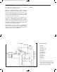
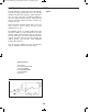
Wiring Sequence:
o 1-29
o 2-30
o 3-44
o 5-72-131
o 6-12-96
o 7-98-126
o 8-11-74-86-88-104-115-117-42-119
o 71-82-116-26
o 27-113
o 28-43-87
o 40-112-91
o 81-92-114-41
o 45-118-73
o 85-103-111-125
o 121-122
o 124-132
o 95-ANT (or 97-ANT)
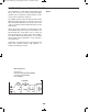
Schematic
Note: The ANT is the 3-meter long
green wire. Connect the one end of the
wire to the spring and hang the wire up
vertically.
EP-130_62315RevC.qxp_EP-130_062812 6/23/15 11:18 AM Page 134