
Manual


-133-
T
he crystal radio is one of the oldest and simplest
radio circuits, which most people in electronics have
experimented with. In the days before vacuum tubes
o
r transistors, people used crystal circuit sets to pick
up radio signals.
Since the crystal radio signals are very weak, you’ll
use a ceramic type earphone to pick up the sounds.
These earphones reproduce these sounds well
because it is and requires little current.
Necessary for receiving distant stations is a good
antenna and earth ground connection is, but you can
hear local stations using almost anything as an
antenna. A long piece of wire (like the green wire in
your kit) makes an acceptable antenna in most
cases. When “earth ground” is referenced it means
just that; you connect the wire to the ground. You can
easy make an earth ground connection by
connecting a wire to a metal cold water pipe. If you
can also drive a metal stake into the ground and
connect the wire to the stake.
Construct the circuit according to the wiring
sequence to use your crystal diode radio. The circuit
has two antenna connections for either short or long
antennas, but only use one at time. Connect short
antennas, 50 feet or less on terminal 95 and longer
antennas on terminal 97. Try out each connection
and use the one that results in the best reception.
Tank circuit is the part of the radio circuit that
includes the antenna coil and the tuning capacitor is
called. When a coil and the tuning capacitor are
connected in parallel, the circuit resonates only at
one frequency. So the circuit picks up only the
frequency that generates the tank circuit to resonate.
The tuning capacitor alters its capacitance as you
rotate it. When the capacitance changes the
resonating frequency of the circuit changes. Thus,
you can tune in various stations by rotating the tuning
capacitor. Without this selectivity, you might hear
several stations mixed together (or only a lot of
noise).
The tank circuit receives high-frequency RF (radio
frequency) signals. The broadcast station uses
sound signals to control the amplitude (strength) of
the RF signals - that is, the height of the RF wave
varies as the sound varies. The diode and the
0.001mF capacitor detect the changes in the RF
amplitude and convert it back to audio signals. The
conversion of amplitude modulation signal into audio
signal is called detection or demodulation.
N
otes:
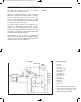
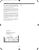
EXPERIMENT #112: CRYSTAL SET RADIO
Schematic
Wiring Sequence:
o 6-12-96
o 7-98-126
o 8-11-90-100-EARPHONE
o 89-99-125-EARPHONE
o 95-ANT or (97-ANT)
g
d
d
Note: The ANT is the 3-meter long
green wire. Connect the one end of the
wire to the spring and hang the wire up
vertically.
EP-130_62315RevC.qxp_EP-130_062812 6/23/15 11:18 AM Page 133