
Manual


-127-
H
ere’s a timer you can use for taking timed tests or
simply for knowing when an amount of time has
p
assed. You can preset this timer for up to
approximately 15 minutes. When the time is up, it
gives out a continuous buzzer sound until you turn
off the power or press the key to reset the circuit.
After you build this experiment, set the control to
position 2 on the dial and slide the switch to position
A to turn on the power. Hold a stopwatch and start it
when you press the key. The timer makes a buzzing
sound in about 30 or more seconds.
Set the control to each division on the dial from 2 to
8, and note how long it takes the timer to produce a
sound. Setting the timer’s calibration - the time that
passes at each setting of the dial - requires a lot of
patience, but it is necessary for making sure your
timer works accurately. After you set the calibration,
you need to make a graph showing each control
position and the time it takes for the buzzer to
sound. Then your tester is ready for use.
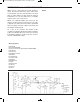
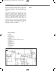
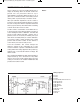
Scan the schematic. The control changes the
reference voltage of the comparator (IC 1). The
resistor R and the capacitor C determine the timer
setting. When the voltage applied to the positive (+)
terminal of IC 1 exceeds the reference voltage, the
alarm sounds.
The operational amplifier has high input impedance
(input resistance), so its current loss is very small,
and you can use it to make a timer with a very long
setting. IC 2 works as an astable multivibrator that
produces the buzzer sound.
N
otes:
EXPERIMENT #107: TIMER
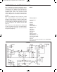
Wiring Sequence:
o 1-29
o 2-30
o 3-114
o 5-83-70-106-118-137-26-121
o 93-63-28-132
o 92-90-64-113
o 65-105-91
o 66-82-84-89
o 67-81
o 94-69-117-138
o 119-124
o 122-131
o 27-68
Schematic
EP-130_62315RevC.qxp_EP-130_062812 6/23/15 11:18 AM Page 127