
Manual


-126-
W
ho says an operational amplifier (op amp) can’t be
used to make a digital circuit? Here, you will use
o
ne to make an AND gate. The LED display is the
output device. If it displays nothing, at least one of
the output signals is logical 0 or low; if it displays H,
they are all logical 1 or high.
When you finish the wiring, turn on the power by
setting the switch to position A. The LED remains
dark. The input terminals are 125, 127, and 129.
These terminals are connected to the negative (–)
terminal, so they do not cause the LED to light.
Terminal 14 is connected to the positive (+) terminal,
so it is the logic 1 terminal. When you connect
terminals 125, 127, and 129 to terminal 14 in
various combinations, you see that the LED lights
and shows H only when terminals 125, 127, and
129 are all connected to terminal 14 - logic 1.
N
otes:
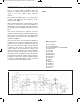
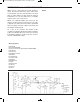
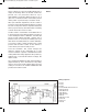
EXPERIMENT #106: OP AMP THREE-INPUT “AND” GATE
Wiring Sequence:
o 14-85-81-63-19-18-21-22-23-132
o 25-47
o 46-88
o 78-76-83-80-70-48-121
o 67-87
o 68-82-84
o 86-69-126-128-130
o 129-75-WIRE
o 127-77-WIRE
o 125-79-WIRE
o 119-124
o 122-131
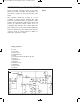
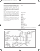
Schematic
EP-130_62315RevC.qxp_EP-130_062812 6/23/15 11:18 AM Page 126