
Manual


-125-
T
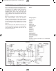
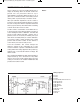
his circuit produces light and sound when it detects
your voice or any other sound. The earphone acts as
a microphone. IC 1 amplifies sounds picked up by
t
he microphone. Diodes Da and Db rectify the
amplified signal - that is, they convert the sound
signal from AC to DC. The signal travels through IC
2, the comparator, and activates the LED and the
speaker.
When you complete the circuit, rotate the control
fully counter-clockwise, and set the switch to
position A. Then rotate the control clockwise while
speaking into the microphone, and set the control in
a position where the LED only lights when you speak
into the microphone. Stop speaking and the LED
turns off.
Now disconnect the wire between 57 and 62, and
reconnect it between 57 and 32. See what happens
to the speaker and LED when you blow into the
microphone (earphone).
N
otes:
EXPERIMENT #105: SUPER SOUND ALARM
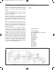
Wiring Sequence:
o 75-63-28-131
o 29-76
o 30-47
o 31-64
o 46-86
o 56-77-110
o 58-59-60-79-78
o 85-80-61-109
o 66-83
o 67-90-73
o 68-89-71
o 87-69-113
o 74-111
o 84-91-115-127
o 112-129-128
o 49-50-51-53-54-135
o 114-13-EARPHONE
o 122-132
o 27-65
o
57-26-121-130-48-116-70-92-88-62-33-72-14-EARPHONE
o 119-124-134
Schematic
EP-130_62315RevC.qxp_EP-130_062812 6/23/15 11:18 AM Page 125