
Manual


-124-
H
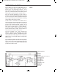
ere’s a DC-DC converter circuit; it can make
5VDC from 3VDC. Assemble the experiment, set
t
he switch to position A, and see how this circuit
works.
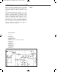
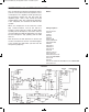
The schematic shows how it works. IC 1 is an
oscillator; its output controls transistor Q1. Self-
induction of the transformer coil generates a high
voltage current. Diode D1 rectifies this voltage and
passes on a high DC voltage current. IC 2 is a
comparator that examines the voltage. When the
input voltage to IC 2 is more than 5V, the LED lights.
How does turning the control affect the circuit? The
control is used as a fixed resistor of 50kW, so
turning the control has no effect.
N
otes:
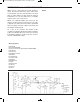
EXPERIMENT #104 DC-DC CONVERTER
Wiring Sequence:
o 3-134
o 5-47-130
o 26-67-72-81
o 28-69-90-92-94
o 31-64
o 33-76-83-86-93-91-70-106-116-48-120
o 46-71-75
o 89-88-63-131
o 84-87-65
o 85-66-115-129
o 82-68-105
o 119-124-135
o 122-132
Schematic
EP-130_62315RevC.qxp_EP-130_062812 6/23/15 11:18 AM Page 124