
Manual


-119-
T
his circuit is a delayed timer that uses an
operational amplifier and the RC time constant. RC
stands for resistor/capacitor. A circuit that delays an
o
peration is a time constant.
Through resistors RA and RB the negative (–)
terminal of the operational amplifier receives a
voltage of about 4.5V. This is the comparator’s
reference voltage. Connected to capacitor C1 is the
positive (+) terminal of the comparator. This
capacitor receives its charge through the series
resistance of R2 and the control. The charging
speed is slower when the resistance is large, and
faster when the resistance is small. This charging
speed set the delay time for the timer circuit.
Now turn the control fully clockwise to position 10.
Set the switch to position A to turn on the power.
LED 1 lights first; LED 2 lights about 5 to 7 seconds
later. This 5 to 7 second time difference is the delay
time that is set by the CR time constant.
Now, turn off the power, set the control fully counter-
clockwise to position 1, and see what happens
when you turn on the power again. LED 2 lights
later than LED 1 again, but how many seconds
later?
N
otes:
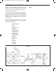
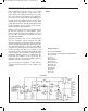
EXPERIMENT #99: RC DELAY TIMER
Schematic
Wiring Sequence:
o 81-31-63-27-131
o 28-87
o 83-33-36-70-116-135-121
o 34-67
o 68-82-84
o 88-69-115-136
o 119-124
o 122-132
EP-130_62315RevC.qxp_EP-130_062812 6/23/15 11:17 AM Page 119