
Manual


-118-
D
o you know what a reset circuit does? It activates
other circuits and detects any power fluctuations in
o
rder to prevent malfunctions. In this experiment,
we change the supply voltage to the circuit with the
switch. The power to the display portion of the
circuit is on, or logic high, when the switch is set to
position A; it is off when the switch is at position B.
When the circuit has been reset the LED display
shows 1.
Let’s start experimenting. First, finish the wiring and
set the switch to position B. Now, with the switch set
to B, the power reset circuit operates under 6V, and
the three LEDs light dimly. The LED display is off,
meaning that the display circuit is not activated.
Now set the switch to position A. You can see the
three LEDs light brightly because the supply voltage
has been modified to 9V. For a moment, the LED
display still shows no change, indicating that the
circuit is being reset. After a short interval, the LED
displays 1 to show that the circuit has finished
resetting and now it is stabilized.
Set the switch to position B to switch the power back
to 6V. You will observe the 1 on the LED disappear,
because now the display circuit is off.
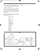
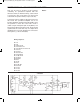
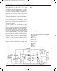
Study the schematic to understand how the circuit
works. The operational amplifier is a comparator.
The 3 LEDs are connected together to make a
reference voltage of about 5.4V for the negative (–)
terminal. With the switch in position B, the positive
(
+) terminal receives about 4.1V, so the comparator
does not allow the display to light. With the switch in
p
osition A, the battery voltage is increased to 9V,
and the 100mF capacitor gradually causes the
comparator’s positive (+) terminal voltage to
increase to about 6V. When this voltage exceeds the
reference voltage of 5.4V, the LED display lights 1.
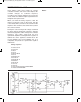
When you set the switch to B, the voltage at the
amplifier’s positive (+) terminal discharges through
the diode, so the voltage is reduced to 4.1V.
Although this circuit seems very simple (consisting
of only one operational amplifier), it is very complex
and important for later use.
Notes:
EXPERIMENT #98: RESET CIRCUIT
Wiring Sequence:
o 21-23-67-116
o 85-70-38-25-121
o 31-68-74
o 32-34
o 35-37
o 73-81-63-129-132
o 86-82-69-115-130
o 119-124
o 122-131
o 123-133
Schematic
EP-130_62315RevC.qxp_EP-130_062812 6/23/15 11:17 AM Page 118