
Manual


-110-
T
his is the operational amplifier version of the
electronic metronome from Project 3 (“Electronic
Metronome”). Slide the switch to position B, and
c
onnect the wires carefully - this project is more
intricate than most of the others. When you
complete assembling the circuit, set the control to
the 12 o’clock position, and slide the switch to
position A to turn on the power. You’ll hear a pip
noise from the speaker at fixed intervals. Now
gradually rotate the control clockwise, and the beats
come faster.
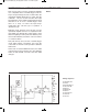
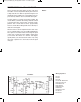
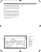
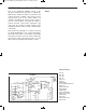
Now observe the schematic. IC 1 and IC 2 are used
as astable multivibrators, as in our last experiment.
But you’ll notice that IC 1 uses diodes to generate
short pulses and the control is used to modify the
speed of the pulses. The transistor turns on each
time a pulse is generated, and creates a sound.
N
otes:
EXPERIMENT #91: OP AMP METRONOME
Wiring Sequence:
o 1-29
o 2-30
o 3-114
o 5-47
o 27-127
o 28-77
o 46-80-84
o 79-70-108-116-48-121
o 63-131
o 89-91-113-64
o 65-90-107
o 86-92-66
o 78-76-83-88-67
o 68-115-125-128
o 82-87-69
o 75-126
o 85-81-119-124
o 122-132
Schematic
EP-130_62315RevC.qxp_EP-130_062812 6/23/15 11:17 AM Page 110