
Manual


-104-
A
microphone can be used to detect sound. Here
you will make a circuit that lights the LED when the
m
icrophone detects sound, using the speaker as a
microphone.
Slide the switch to position B and construct the
circuit. When you finish the wiring, by sliding the
switch to position A to turn on the power. Now talk
into the “microphone” (the speaker) or tap it lightly;
the LED blinks.
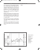
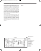
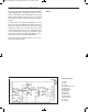
Observe the schematic. IC1 is configured as a non-
inverting amplifier with a gain of about 100, and it
amplifies the signal from the microphone (the
speaker). IC2 is configured as a comparator,
comparing the output of IC1 to a reference voltage
from the battery. When IC1’s output exceeds the
reference voltage, the comparator output goes low,
and the LED lights.
N
otes:
EXPERIMENT #85: VOICE-CONTROLLED LED
Schematic
Wiring Sequence:
o 1-29
o 2-30
o 3-110
o 5-76-74-80-70-121
o 85-31-63-132
o 33-64
o 79-65-112
o 73-86-66
o 90-67-111
o 89-68-115
o 69-109
o 75-116
o 119-124
o 122-131
EP-130_62315RevC.qxp_EP-130_062812 6/23/15 11:17 AM Page 104