
Manual


-103-
Y
ou know that digital circuits produce low or high (L
or H) outputs (0 or 1). Now you’re going to create a
logic tester that shows 1 for high level (H) and 0 for
l
ow level (L) on the LED display.
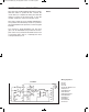
Slide the switch to position B and construct the
circuit. When you finish the wiring, slide the switch
to position A to turn on the power. The number 0 is
on the display because the test terminal (terminal
13) is at low level when no input is exerted. Attach
the test terminal-to-terminal 122 to apply +4.5V. The
display alters to 1.
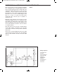
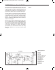
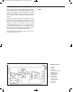
View the schematic. The operational amplifier works
as a comparator. The 22kW and 10kW resistors
produce a reference voltage of 3V at its negative (-
) input terminal. When the voltage at its positive (+)
terminal exceeds this reference voltage, the
comparator’s output level goes high, turning off
transistor Q1. Now segments A, D, E, and F on the
display turn off, leaving a 1 on the display.
N
otes:
EXPERIMENT #84: LOGIC TESTING CIRCUIT
Wiring Sequence:
o 17-18-19-20-44
o 86-79-63-21-23-45-132
o 43-80-82
o 67-81
o 68-83-85
o 119-124
o 122-131
o 69-89-13-CHECK POINT
o 121-25-70-90-84-14-CHECK POINT
Schematic
EP-130_62315RevC.qxp_EP-130_062812 6/23/15 11:17 AM Page 103