
Manual


-101-
N
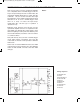
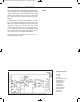
ow you are going to use the operational amplifier
as a comparator and as a Schmitt trigger circuit. As
long as its input voltage exceeds a certain value, the
o
perational amplifier will produce a signal. View the
schematic: can you see how it works? The input
level that turns on the output is higher than the level
than turns it off. So once a Schmitt trigger circuit
turns on, it stays on unless the input drops
significantly. We call this type of operation a
“hysteresis loop.”
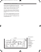
Build the circuit, but don’t press the key yet. The
operational amplifier serves as a comparator in this
state. When you alternate the control, LEDs 1 and 2
take turns lighting at some point. Note that this point
doesn’t alter whether you turn the control clockwise
or counterclockwise.
Now push the key and you have a Schmitt trigger
circuit, which makes a hysteresis loop. Turn the
control and see how the circuit operation is different
from before.
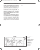
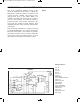
As the ratio of resistors RB/RA increases, the width
of hysteresis becomes narrower. Try using different
values for RA and RB, and notice how the width
changes.
N
otes:
EXPERIMENT #82: INTRODUCING THE SCHMITT TRIGGER
Wiring Sequence:
o 70-36-26-121
o 27-83
o 63-28-130-131
o 34-33-67-90
o 68-134
o 84-69-138
o 89-137
o 119-124-135
o 122-132
o 31-129
Schematic
EP-130_62315RevC.qxp_EP-130_062812 6/23/15 11:17 AM Page 101