EP-130_62315RevC.qxp_EP-130_062812 6/23/15 11:16 AM Page 1 ELECTRONIC PLAYGROUND TM and LEARNING CENTER MODEL EP-130 ELENCO Wheeling, IL, USA Copyright © 2015, 2009 by Elenco® Electronics, Inc. All rights reserved. ® REV-C Revised 2015 No part of this book shall be reproduced by any means; electronic, photocopying, or otherwise without written permission from the publisher.
EP-130_62315RevC.qxp_EP-130_062812 6/23/15 11:16 AM Page 2 Important: If you encounter any problems with this kit, DO NOT RETURN TO RETAILER. Call toll-free (800) 5332441 or e-mail us at: help@elenco.com. Customer Service • 150 Carpenter Ave. • Wheeling, IL 60090 U.S.A. WARNING: Always check your wiring before turning on a circuit. Never leave a circuit unattended while the batteries are installed. Never connect additional batteries or any other power sources to your circuits.
EP-130_62315RevC.qxp_EP-130_062812 6/23/15 11:16 AM Page 3 VI. MEET TRANSISTOR-TRANSISTOR LOGIC 48. Blinking LEDs 49. Machine Sound 50. Astable Multivibrator Using TTL 51. Tone Generator 52. Monster Mouth 53. Dark Shooting 54. A One-Shot TTL 55. Transistor Timer Using TTL 56. LED Buzzing 57. Another LED Buzzing 58. Set/Reset Buzzer 59. Another Set/Reset Buzzer VII. OSCILLATOR APPLICATION CIRCUITS 60. Ode to the Pencil Lead Organ 61. Double-Transistor Oscillator 62. Decimal Point Strobe Light 63.
EP-130_62315RevC.qxp_EP-130_062812 6/23/15 11:16 AM Page 4 BEFORE YOU START THE FUN! As you will notice we refer to a Volt / Ohm Meter (VOM) for making measurements. A VOM or multimeter is a instrument that measures voltage, current (amperes or amps), and resistance (ohmsW). You will learn more about these in the upcoming pages. If you really want to learn about electronic circuits, it is vital that you learn how to measure circuit values - for only then will you really understand electronic circuitry.
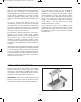
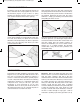
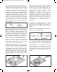
EP-130_62315RevC.qxp_EP-130_062812 6/23/15 11:16 AM Page 5 WIRING CONNECTIONS Provided in your kit are spring terminals and pre-cut wires, make the wires snap together for your use in the numerous projects. To join a wire to a spring terminal, just directly bend the spring over to one side and then install the wire into the opening. Only insert the exposed or shiny part of the wire into the spring terminal.
EP-130_62315RevC.qxp_EP-130_062812 6/23/15 11:16 AM Page 6 fine screen would keep rocks from falling over), which would prolong the flow of water but not stop it completely. Like rocks are for water, resistors work in a similar way. They regulate how much electric current flows. The resistance, is expressed in ohms (W, named in honor of George Ohm), kilohms (kW, 1,000 ohms) or megohms (MW, 1,000,000 ohms) is a determination of how much resistor resists the flow of electricity.
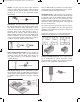
EP-130_62315RevC.qxp_EP-130_062812 6/23/15 11:16 AM Page 7 Diodes: Are like one-way streets. They allow the current to flow in only one direction. There are three of these in your kit. Your kit contains one silicon diode (marked Si) as well as two germanium diodes (marked Ge). The “8” LED display is mounted on a board and to prevent burning out the display with excess current, permanent resistors have been wired in.
EP-130_62315RevC.qxp_EP-130_062812 6/23/15 11:16 AM Page 8 Antenna: This cylindrical component with a coil of fine wire wrapped around it is a radio antenna. If you’re wondering what the dark colored rod is, it’s actually mostly powdered iron. It’s also known as a “Ferrite Core”, which is efficient for antennas, and used in almost all transistor radios. energy from an AC electrical signal it creates mechanical vibration.
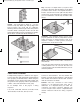
EP-130_62315RevC.qxp_EP-130_062812 6/23/15 11:16 AM Page 9 Key: The key is a simple switch—you press it and electricity is allowed to flow through the circuit. When you release it, the circuit is not complete because a break is caused in the circuit’s path. The key will be used in most circuits often times in signaling circuits (you can send Morse code this way as well as other things). Switch: You know what a switch is – you use switches every day.
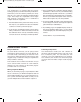
EP-130_62315RevC.qxp_EP-130_062812 6/23/15 11:16 AM Page 10 TROUBLESHOOTING You should have no problem with the projects working properly if you follow the wiring instructions. However, if you do encounter a problem you can try and fix it by using the following troubleshooting steps. These steps are comparable to those steps that electronic technicians use to troubleshoot complex electronic equipment. 3.
EP-130_62315RevC.qxp_EP-130_062812 6/23/15 11:16 AM Page 11 I.
EP-130_62315RevC.qxp_EP-130_062812 6/23/15 11:16 AM Page 12 EXPERIMENT #1: WOODPECKER Notes: For your first experiment you are going to make a circuit that sounds like a woodpecker chirping. Follow the wiring sequence carefully and observe the drawings. Don’t forget to make all the proper connections and have fun! The simple circuit shown here does not have a key or a switch, but you can easily add one. Replace connection 124-28 with connections 124-137 and 138-28 to connect the key.
EP-130_62315RevC.qxp_EP-130_062812 6/23/15 11:16 AM Page 13 EXPERIMENT #2: POLICE SIREN Notes: Here is the first siren you are going to do – don’t be shocked if this experiment becomes the most famous circuit in this kit. This siren sounds like a real siren on a police car! After the wiring is competed press the key. The tone you eventually hear gets higher after pressing the key. When you release the key, the tone gets lower and then fades out. Try some of these modifications: 1.
EP-130_62315RevC.qxp_EP-130_062812 6/23/15 11:16 AM Page 14 EXPERIMENT #3: METRONOME Notes: Learning to play a musical instrument? Then you might find this experiment helpful. This is an electronic version of the metronome, used by musical students and musical geniuses alike, worldwide. If you press the key, you hear a repeating sound from the speaker. Turn the control knob to the right and you’ll hear the sound “get faster” as the time between sounds shortens. Try swapping out the 4.
EP-130_62315RevC.qxp_EP-130_062812 6/23/15 11:16 AM Page 15 EXPERIMENT #4: GRANDFATHER CLOCK Does your home lack a grandfather clock? Well not any longer, with this experiment you will make your own electronic grandfather clock. Notes: This circuit will produce clicks at approximately onesecond intervals. The sound and timing together might remind you of an old grandfather clock. If you would like for it to go faster or slower then you can change out the 100kW resistor.
EP-130_62315RevC.qxp_EP-130_062812 6/23/15 11:16 AM Page 16 EXPERIMENT #5: HARP Notes: Have you ever wanted to make music just by waving your hand? Well that is just what you are going to be doing. How does this magic work? Well, the tones change based upon the amount of light that gets to the CdS cell. With a bright light the tone is higher but, if you cover the CdS with your hand, the sound gets lower. Since the early days of vacuum-tube circuitry, this method of creating musical sound has been used.
EP-130_62315RevC.qxp_EP-130_062812 6/23/15 11:16 AM Page 17 EXPERIMENT #6: TWEETING BIRD Notes: In this experiment you are going to make a circuit that sounds like the mockingbird. Follow the wiring sequence and observe the drawings. Don’t forget to make all the proper connections and have fun! To finish the circuit below, slide the switch to the A position to turn on the power. No sound will come from the speakers yet.
EP-130_62315RevC.qxp_EP-130_062812 6/23/15 11:16 AM Page 18 EXPERIMENT #7: MEOWING CAT Notes: Are you bothered by mice, do you not have a mousetrap? You should try this next experiment to help you instead—see if the sound of this cat can keep the pests out of your life. Just follow the drawing below and the wiring sequence. To start the experiment switch the set to B. Press down on the key and release it immediately. You will hear the meow from the cat coming from the speaker.
EP-130_62315RevC.qxp_EP-130_062812 6/23/15 11:16 AM Page 19 EXPERIMENT #8: CALLING’ FISH Notes: Did you know that many marine animals communicate to each other using sound? I bet you have heard that dolphins and whales use sound for communication, but what you probably don’t know is that they are not the only ones. Due to research we are able to find out that some fish are attracted to certain sounds. Making this circuit, will allow you do to some research of your own.
EP-130_62315RevC.qxp_EP-130_062812 6/23/15 11:16 AM Page 20 EXPERIMENT #9: STROBE LIGHT Notes: In this experiment you will be creating an oscillator circuit that doesn’t make sound using a speaker or an earphone. Instead the circuit will produce light with an LED. This will give you an idea of how larger strobe lights work. When you press the key, watch LED 1. At certain intervals the light turns on and off. With the 50kW control you can control the rate of blinking.
EP-130_62315RevC.qxp_EP-130_062812 6/23/15 11:17 AM Page 21 EXPERIMENT #10: SOUND EFFECTS FOR HORROR MOVIES Frequency modulation, or FM, is when the frequency of an oscillator is controlled by part of the circuit. An FM radio signal is similar to this but at higher frequencies. The sounds that you will hear from this circuit will remind you of the music you hear in horror movies.
EP-130_62315RevC.qxp_EP-130_062812 6/23/15 11:17 AM Page 22 EXPERIMENT #11: MACHINE GUN OSCILLATOR This circuit is what engineers refer to as a “pulse oscillator”. It will make machine gun like sounds. Once you finish wiring, press the key to start the oscillator. The 50kW resistor is the control; you can swap it out with other resistors to change the sound from a few pulses per second to a dozen or so per second.
EP-130_62315RevC.qxp_EP-130_062812 6/23/15 11:17 AM Page 23 EXPERIMENT #12: MOTORCYCLE MANIA Have you ever tried to steer a bicycle or a motorcycle with just four fingers? This would be dangerous on a real motorcycle but on electronic version it is a lot of fun! To do this project, connect the components following the wiring sequence. Next grasp the metal exposed ends of the two long wires (connected to terminals 110 and 81) in between your index finger and thumb of your left and right hands.
EP-130_62315RevC.qxp_EP-130_062812 6/23/15 11:17 AM Page 24 EXPERIMENT #13: VISION TEST Notes: This circuit produces short pulses. After you close the key, the LED display shows 1 for a second and then turns off, even when you keep pressing the key. You could create a game with this circuit. Display a number or a letter on the LED display and then have the players tell you what number it is. You change numbers or letters on the display by just changing the wiring to the display.
EP-130_62315RevC.qxp_EP-130_062812 6/23/15 11:17 AM Page 25 EXPERIMENT #14: PATROL CAR SIREN With this experiment you may want to be careful not to confuse your neighbors. This experiment sounds as like a loud siren just like the real sirens on police cars and ambulances. The tone is initially high but as you close the key the tone gets lower. You are able to control the tone just as the police and ambulance drivers do.
EP-130_62315RevC.qxp_EP-130_062812 6/23/15 11:17 AM Page 26 II.
EP-130_62315RevC.qxp_EP-130_062812 6/23/15 11:17 AM Page 27 A MAJOR CHANGE Until now, in addition to the wiring sequences you have had drawings to help guide you in the wiring connections. The rest of the projects will have just the schematic diagram without the circuit drawings. As you will start to notice, the schematics have some lines that cross each other and that there is a dot at the crossing point.
EP-130_62315RevC.qxp_EP-130_062812 6/23/15 11:17 AM Page 28 EXPERIMENT #15: LIGHT DIMMER Hint: the 10mF capacitor charges when you close the key. Ever thought you could use a capacitor to dim a light? Try this project. After you finish the wiring, set the switch to A. Then the LED segments will light up slowly and show an L. Once the LED reaches its brightest point it will stay on. Move the switch to B and watch as the L fades away. Notes: Look at the schematic.
EP-130_62315RevC.qxp_EP-130_062812 6/23/15 11:17 AM Page 29 EXPERIMENT #16: FLIP FLOPPING Notes: How about we take a break? This circuit is for entertainment. The numbers 1 and 2 will flash on the display in the circuit. This might remind you of some neon signs that have eye-catching advertisements on them. A “flip-flop” circuit controls the LED display in this experiment. In later projects you will be learning more about flip-flop circuits.
EP-130_62315RevC.qxp_EP-130_062812 6/23/15 11:17 AM Page 30 EXPERIMENT #17: CAPACITOR DISCHARGE FLASH produced when the charge held by the capacitor is released into the transformer. In this circuit single pulses of high voltage electric energy are generated by suddenly discharging a charged capacitor through a transformer. Automobile ignition systems use a similar capacitordischarge reaction.
EP-130_62315RevC.qxp_EP-130_062812 6/23/15 11:17 AM Page 31 EXPERIMENT #18: TRANSISTOR ACTION There are three connections made on a transistor; one of these (the base) controls the current between the other two connections. The important rule to remember for transistors is: a transistor is turned on when a certain voltage is applied to the base. A positive voltage turns on an NPN type transistor. A negative voltage turns on a PNP type transistor.
EP-130_62315RevC.qxp_EP-130_062812 6/23/15 11:17 AM Page 32 EXPERIMENT #19: SERIES AND PARALLEL CAPACITORS Some of the handiest items in your kit are the capacitors. They store electricity, smooth out pulsing electricity into a steady flow and let some electric current flow while blocking other current. This circuit allows you to compare the effects of capacitors connected in both series and parallel. smallest capacitor in the series connection. The higher-pitch sound is caused by the lower capacitance.
EP-130_62315RevC.qxp_EP-130_062812 6/23/15 11:17 AM Page 33 EXPERIMENT #20: TRANSISTOR SWITCHING In this experiment you study the switching action of transistors in turning an LED on. You will be using two different transistors - one of the two PNP types and the NPN type included in your kit. PNP and the NPN refers to the arrangement of the semiconductor materials inside the transistors. Next, change the resistors to 10kW and then press the key. Use terminals 83 and 84 and terminals 81 and 82.
EP-130_62315RevC.qxp_EP-130_062812 6/23/15 11:17 AM Page 34 EXPERIMENT #21: SERIES AND PARALLEL RESISTORS together, and then divide the product by the sum of values. In this case, the total resistance is: In this project, you will discover what happens when you connect resistors in series and in parallel. You will see the LED-1 on the panel flash on and off when you finish wiring. 470 x 100 (470 + 100) See what happens to the LED on side A and then on side B when you slide the switch.
EP-130_62315RevC.qxp_EP-130_062812 6/23/15 11:17 AM Page 35 EXPERIMENT #22: AMPLIFY THE SOUND A two-transistor amplifier is used in this circuit. In an amplifier, a small signal is used to produce or control a large signal. This circuit is similar to an early model transistor hearing aid amplifier. Notes: Your kit’s speaker can change sound pressure into a weak voltage. The transformer increases the voltage, and which is then applied to the NPN transistor through the 3.3mF capacitor.
EP-130_62315RevC.qxp_EP-130_062812 6/23/15 11:17 AM Page 36 III.
EP-130_62315RevC.qxp_EP-130_062812 6/23/15 11:17 AM Page 37 EXPERIMENT #23: LED DISPLAY BASICS By using the LED display you will see the effect of electrical signals. An LED is similar to a normal diode except when current flows through it, it emits light. One example of the LED display is a power indicator on your DVD player or your radio that tells you the power is on. Do the following experiment to experience how fast the LED operates. 1. Do not close the key but hook up the circuit. 2.
EP-130_62315RevC.qxp_EP-130_062812 6/23/15 11:17 AM Page 38 EXPERIMENT #24: DIGITAL DISPLAY CIRCUIT FOR THE SEVEN-SEGMENT LED Notes: Wire the circuit as shown to connect the 3V supply to the LED segments and the decimal point (Dp). What numbers and letters do you see displayed? In this experiment you can make some voltage measurements using a Voltage/Ohm Meter (VOM) if you have one. Connect the VOM as directed by its instructions. Skip these measurements if you do not have a VOM.
EP-130_62315RevC.qxp_EP-130_062812 6/23/15 11:17 AM Page 39 EXPERIMENT #25: LED DISPLAY WITH CdS AND TRANSISTOR Notes: In this project you will see how to turn on an LED by using a transistor and a CdS cell. Think of the CdS cell as a resistor that changes its resistance based upon the amount of light that falls upon it. In the dark the resistance is very high, around 5 megohms (MW, 5 million ohms); in bright sunlight, it can decrease to about 100W or less.
EP-130_62315RevC.qxp_EP-130_062812 6/23/15 11:17 AM Page 40 EXPERIMENT #26: SWITCHING THE LED DISPLAY USING TRANSISTOR CONTROL Notes: This project shows how to control the LED display through the use of transistors. This circuit is similar to the one in Project 18 (Transistor Action). The differences between these two are the position of the switch as well as the value of the resistor. In this project we use the base circuit of the NPN transistor as a switch, in order to control the cathode of the LED.
EP-130_62315RevC.qxp_EP-130_062812 6/23/15 11:17 AM Page 41 IV.
EP-130_62315RevC.qxp_EP-130_062812 6/23/15 11:17 AM Page 42 EXPERIMENT #27: “FLIP-FLOP” TRANSISTOR CIRCUIT What is a flip-flop? It is a kind of circuit that changes back and forth between two states (on and off) at specific intervals. It flips into one state and flops into another and so on. Transistor Q1 turns on when the charge drops to a specific point, the negative voltage from the 47kW resistor. Once Q1 turns on, and 100mF quickly starts charging and transistor Q2 turns off.
EP-130_62315RevC.qxp_EP-130_062812 6/23/15 11:17 AM Page 43 EXPERIMENT #28: “TOGGLE FLIP-FLOP” TRANSISTOR Now it is time to step into the world of digital circuits and learn some basics. A circuit that acts as a switch to turn different components off and on is a digital circuit. In this section you will be dealing with diode-transistor logic (DTL) circuits- these are circuits that use diodes and transistors to turn the power on and off. Once you have completed the wiring, set the switch to A.
EP-130_62315RevC.qxp_EP-130_062812 6/23/15 11:17 AM Page 44 EXPERIMENT #29: “AND” DIODE TRANSISTOR LOGIC WITH LED DISPLAY In this circuit you will first learn about the AND circuit. When all the connections to its terminals are logic high (receiving voltage), the AND circuit produces a high output. The base of the PNP transistor turns on when both of the inputs are high and when both diodes supply negative voltage to the base of the PNP transistor.
EP-130_62315RevC.qxp_EP-130_062812 6/23/15 11:17 AM Page 45 EXPERIMENT #30: “OR” DTL CIRCUIT WITH DISPLAY This next circuit is a logic OR circuit. Are you able to guess how this circuit may work? Remember that the AND circuit produces high logic only when inputs A and B are both high. In the OR circuit logic high is produced when A or B receives a logic high input. notes of their similarities and their differences. On the schematics diagram see if you can follow the circuit.
EP-130_62315RevC.qxp_EP-130_062812 6/23/15 11:17 AM Page 46 EXPERIMENT #31: “NAND” DTL CIRCUIT WITH DISPLAY Notes: You will not be able to find the word NAND in your dictionary (unless it is a computer or electronic dictionary). This term means inverted or Non-AND function. It creates output conditions that are the opposite of the AND circuits output conditions. When both inputs A and B are high the NAND output is low. If either or both of the inputs are low then the output is high.
EP-130_62315RevC.qxp_EP-130_062812 6/23/15 11:17 AM Page 47 EXPERIMENT #32: “NOR” TRANSISTOR CIRCUIT WITH DISPLAY Notes: It is easy to determine what the NOR (inverted OR) circuit does now that you have built and learned about the NAND (inverted AND) circuit. When either terminal A or B is connected to terminal H (119) the display shows L. When low inputs are received by terminals both A and B then the circuit output is high. In the OR circuit this is the opposite.
EP-130_62315RevC.qxp_EP-130_062812 6/23/15 11:17 AM Page 48 EXPERIMENT #33: “EXCLUSIVE OR” DTL CIRCUIT Notes: If you don’t know what an exclusive OR means, don’t worry. An exclusive OR (abbreviated XOR) circuit provides a high output only when one or the other of its inputs are high. You can see that an XOR circuit produces a low output, only if both of the inputs are the same (high or low). If the inputs are different (either high and low or low and high) it results in the output being high.
EP-130_62315RevC.qxp_EP-130_062812 6/23/15 11:17 AM Page 49 V.
EP-130_62315RevC.qxp_EP-130_062812 6/23/15 11:17 AM Page 50 EXPERIMENT #34: “BUFFER” GATE USING TTL Have you ever wondered what happens once you start adding digital circuits together, using the output of one as the input of another? You’ll find out when you build this project. 1 is the input when the switch is set to A, and 0 is the input when the switch is at B. When the input to the first NAND is 1, its output is 0. But the 0 output of the first NAND is the input to the second.
EP-130_62315RevC.qxp_EP-130_062812 6/23/15 11:17 AM Page 51 EXPERIMENT #35: “INVERTER” GATE USING TTL Notes: A circuit that has an output that is the opposite of its input is called an inverter. If the output is 0, (low) then the input is 1 (high). If the output is 1, then the input is 0. Before completing this project set the switch to A. Next, connect terminals 13 and 14. You’ll observe that both LED 1 and LED 2 are off. Since the input is 1, the output has to be 0.
EP-130_62315RevC.qxp_EP-130_062812 6/23/15 11:17 AM Page 52 EXPERIMENT #36: “AND” GATE USING TTL Notes: By using your kit’s NAND gates, are you able to figure out how to make an AND gate? To find out let’s experiment! As you build this circuit, leave the switch at B. connect terminals 13 and 14 to turn the power on once you have finished. Now press the key. What happens to LED 1? Now while pressing the key, set the switch to A.
EP-130_62315RevC.qxp_EP-130_062812 6/23/15 11:17 AM Page 53 EXPERIMENT #37: “OR” GATE USING TTL Notes: One of the cool things about the quad two-input NAND IC is that to make up other logic circuits all we have to do is combine the four NAND gates. In our last two projects you have been shown how you are able to use NANDs to make up some other logic circuits. In this project you will be shown how to make up an OR gate from the NAND gates.
EP-130_62315RevC.qxp_EP-130_062812 6/23/15 11:17 AM Page 54 EXPERIMENT #38: “R-S FLIP-FLOP” USING TTL Notes: R-S does not mean Radio Shack® flip-flop. As we mentioned earlier circuits that flip-flop alternate between two states. Those who use flip-flop circuits most often are engineers, and they use flip-flop circuits to switch between low (0) and high (1) outputs. We say a circuit is at set status (S) when the output is high or on. We use the word rest (R) when a circuit is off.
EP-130_62315RevC.qxp_EP-130_062812 6/23/15 11:17 AM Page 55 EXPERIMENT #39: “TRIPLE-INPUT AND” GATE USING TTL We have been using digital circuits that have two inputs, but that doesn’t mean that we can’t have more than the two inputs. Here is a TTL AND gate which has three inputs. Use the schematic to try and figure out how to have three inputs result in an output of 1. The circuit works this way: connected to the one NAND are both the key and the switch.
EP-130_62315RevC.qxp_EP-130_062812 6/23/15 11:17 AM Page 56 EXPERIMENT #40: “AND” ENABLE CIRCUIT USING TTL Notes: Setting the switch to B blocks the channel from the LED 1 to the LED 2 However, when you set the switch to A, you will find that LED lights and turns off at the same time as LED 1. The two NAND gates produce an AND gate. In this circuit the LED 1 is known as the data input. The output is the LED 2. Frequently these terms are used with enable circuits.
EP-130_62315RevC.qxp_EP-130_062812 6/23/15 11:17 AM Page 57 EXPERIMENT #41: “NAND” ENABLE CIRCUIT USING TTL NAND gates are able to act as electronic guardsmen. If you don’t want a signal to be placed into input of a circuit, a NAND will make sure that it doesn’t happen. the two inputs to the NAND equivalent to 1 once the switch is set to A. The multivibrator sends 0 and then signals to the other NAND input.
EP-130_62315RevC.qxp_EP-130_062812 6/23/15 11:17 AM Page 58 EXPERIMENT #42: “NOR” GATE USING TTL Notes: Try to mark 0 and 1 inputs on the schematic and see if this circuit comes up at either a 0 or 1 output. Give it try and don’t peak at the answer. As you are constructing this circuit, make sure to have the switch set to B. Once you have completed the wiring, connect to terminals 13 and 14. Now press the key. Are there any changes in LED 1? Now release the key and place the switch to A.
EP-130_62315RevC.qxp_EP-130_062812 6/23/15 11:17 AM Page 59 EXPERIMENT #43: “NAND” GATE MAKING A TOGGLE FLIP-FLOP Notes: If you are thinking that the NAND gate is a truly versatile circuit, well then your right! This experiment is a toggle flip-flop circuit made by using four NAND gates. When you have finished building this circuit, connect terminals 13 and 14 in order to turn the power on. Slowly press the key several times. You will notice that each time the key is pressed the LED 1 turns on.
EP-130_62315RevC.qxp_EP-130_062812 6/23/15 11:17 AM Page 60 EXPERIMENT #44: “EXCLUSIVE OR” GATE USING TTL Notes: Since we have made up some digital circuits by combining NAND gates, it makes sense that we make XOR gates too. This circuit will show you how. Before you complete this circuit set the switch to B. Connect the terminals 13 and 14, once you have finished the wiring. Does anything happen to LED 1 when you press the key? Release the key now and set the switch to A.
EP-130_62315RevC.qxp_EP-130_062812 6/23/15 11:17 AM Page 61 EXPERIMENT #45: “OR” ENABLE CIRCUIT USING TTL Notes: Have you figured out how to make an enable circuit using an OR gate? Well, if the answer is yes, then this is your chance to compare you design to our OR enable circuit. As done in projects 35 and 36, the multivibrator provides the input to the OR gate in this circuit.
EP-130_62315RevC.qxp_EP-130_062812 6/23/15 11:17 AM Page 62 EXPERIMENT #46: LINE SELECTOR USING TTL Notes: It isn’t hard to think of some situations where we might want to send input data to two or more different outputs. This experiment shows how we can use a network of NAND gates to help do that. This circuit uses three NAND gates and a multivibrator. Build the circuit, connecting terminals 13 and 14 last.
EP-130_62315RevC.qxp_EP-130_062812 6/23/15 11:17 AM Page 63 EXPERIMENT #47: DATA SELECTOR USING TTL The last experiment you did let you explore how data could be sent to two or more different outputs. You can probably think of situations where we might want to or need to do the opposite - which is sending data from two different sources of output. This circuit shows you how. Computers use a more complex version of these circuits.
EP-130_62315RevC.qxp_EP-130_062812 6/23/15 11:17 AM Page 64 VI.
EP-130_62315RevC.qxp_EP-130_062812 6/23/15 11:17 AM Page 65 EXPERIMENT #48: BLINKING LEDS Notes: Connect terminals 13 and 14 to turn on the power and finish the wiring sequence for this circuit. You’ll notice that both LED 1 and LED 2 alternate going on and off. By substituting different values for the 100mF capacitor you can change the speed of the blinking. In place of transistor multivibrators, TTL multivibrators are becoming widely used today.
EP-130_62315RevC.qxp_EP-130_062812 6/23/15 11:17 AM Page 66 EXPERIMENT #49: MACHINERY SOUND Listen to the sound this project makes. Take your time and check your work because there are a lot of wiring steps. Once you’ve finished, set the switch to position A. What are you hearing? From looking at the schematic, can you explain how the circuit produces this sound? Notes: This circuit has two multivibrators, one with PNP transistors, and one built with NAND gates.
EP-130_62315RevC.qxp_EP-130_062812 6/23/15 11:17 AM Page 67 EXPERIMENT #50: ASTABLE MULTIVIBRATOR USING TTL Notes: multivibrator – are you able guess what astable means? Generate a guess, and complete this project to see if you were right. To turn the circuit on, connect terminals 13 and 14. LED 1 begins to flash. Astable means the multivibrator’s output keeps switching back and forth between 0 and 1. So far most of the multivibrators that you have built do the same things.
EP-130_62315RevC.qxp_EP-130_062812 6/23/15 11:17 AM Page 68 EXPERIMENT #51: TONE GENERATOR USING TTL Notes: We’ve been constructing tones with audio oscillators for so long that it might seem as if there’s no other way to produce tones from electronic circuits. Multivibrators made from NAND gates do the job just as well. Connect the earphone to terminals 13 and 14 and set the switch to A to turn on the power once you finish wiring this circuit.
EP-130_62315RevC.qxp_EP-130_062812 6/23/15 11:17 AM Page 69 EXPERIMENT #52: MONSTER MOUTH Notes: Do you know of someone who is a big mouth? (Or, have you ever been accused of being one?) This experiment lets you and your friends see who’s got the most ear-splitting voice. How does this work? When you yell, you create sound waves, which are actually variations in air pressure. These air pressure variations create pressure on the crystalline structure in the earphone.
EP-130_62315RevC.qxp_EP-130_062812 6/23/15 11:17 AM Page 70 EXPERIMENT #53: DARK SHOOTING Notes: Think you have good night vision? This experiment is a game that lets you find out how well you can see in the dark. In a completely dark room, it tests your aim! Once you have completed this project, put it in as dark of a room as possible. Slide the switch to position A and modify the control in a counterclockwise direction until LED 1 and LED 3 light. Now it is time to test your ability.
EP-130_62315RevC.qxp_EP-130_062812 6/23/15 11:17 AM Page 71 EXPERIMENT #54: A ONE-SHOT TTL Notes: What does “one-shot” mean to you? Turn the switch to A, and see what happens to LED 1 when you press the key once at a time. Try holding the key down for different periods while watching LED 1. Does LED 1 stay on the same length of time or does it change? Regardless of the length of the input, you see that a one-shot multivibrator has an output for a certain length of time. (It “fires one shot.
EP-130_62315RevC.qxp_EP-130_062812 6/23/15 11:17 AM Page 72 EXPERIMENT #55: TRANSISTOR TIMER USING TTL Notes: This is another type of one-shot circuit; in this project you hear the effects of the multivibrator. From the schematic you can see that this experiment uses a combination of simple components and digital electronics. Once you press the key, the 100mF capacitor is charged and lets the NPN translator in the left corner of the schematic operate.
EP-130_62315RevC.qxp_EP-130_062812 6/23/15 11:17 AM Page 73 EXPERIMENT #56: LED BUZZING Notes: This is another circuit that uses both transistor and NAND type multivibrators. As you hear a sound through the earphone you see LED 1 light up. Build the circuit, connect the earphone to terminals 13 and 14, and set the switch to position A. Each time the LED lights up you’ll hear a pulse in the earphone.
EP-130_62315RevC.qxp_EP-130_062812 6/23/15 11:17 AM Page 74 EXPERIMENT #57: ANOTHER LED BUZZING Notes: Carefully compare the schematic for this experiment with the schematic for the last experiment. While they are similar in many ways, but there’s a critical difference. Can you find what it is? Can you tell how the operation will be different? Attach the earphone to Terminals 13 and 14 and set the switch to position A. You will hear nothing in the earphone but you should find that LED 1 lights up.
EP-130_62315RevC.qxp_EP-130_062812 6/23/15 11:17 AM Page 75 EXPERIMENT #58: SET/RESET BUZZER Does anything look familiar about the schematic for this project? This circuit uses an R-S flip-flop circuit made from NAND gates, comparable to the circuit in experiment 38 (R-S Flip-Flop using TTL). Notes: Circuits like this are used in alarms. Since intruders usually can’t figure out how to make them stop, they are extremely useful.
EP-130_62315RevC.qxp_EP-130_062812 6/23/15 11:17 AM Page 76 EXPERIMENT #59: ANOTHER SET/RESET BUZZER Notes: Here’s a variant of the last project. This time we use an R-S flip-flop made with transistors and a NAND multivibrator. You will hear a sound in the earphone when you set the switch to B and press the key. No matter how many times you press the key you can still hear the sound. The sound will stop when you set the switch to A and press the key.
EP-130_62315RevC.qxp_EP-130_062812 6/23/15 11:17 AM Page 77 VII.
EP-130_62315RevC.qxp_EP-130_062812 6/23/15 11:17 AM Page 78 EXPERIMENT #60: ODE TO THE PENCIL LEAD ORGAN Notes: This experiment is an oscillator that is controlled in an abnormal way: with a pencil mark! You have caught a glimpse in other oscillator projects how changing the circuit’s resistance can change the sound that is produced.
EP-130_62315RevC.qxp_EP-130_062812 6/23/15 11:17 AM Page 79 EXPERIMENT #61: DOUBLE-TRANSISTOR OSCILLATOR Notes: Now you will build an oscillator using two transistors connected directly to each other. As you have witnessed, there are many ways to make an oscillator. This way is easier compared to some. After finishing the wiring, press the key. You hear a beep sound coming from the speaker. Now rotate the control.
EP-130_62315RevC.qxp_EP-130_062812 6/23/15 11:17 AM Page 80 EXPERIMENT #62: DECIMAL POINT STROBE LIGHT Notes: This circuit is an oscillator with a slow frequency, and you can see the LED lighting and turning off. The off time is longer than the on time, so you observe short pulses of light with long periods between them. The wiring sequence below will make the decimal point light, however you can light any part of the LED display.
EP-130_62315RevC.qxp_EP-130_062812 6/23/15 11:17 AM Page 81 EXPERIMENT #63: “THE EARLY BIRD GETS THE WORM” Notes: This is the electronic bird circuit that you built for Project 6 (The Woodpecker), but now it has a photoelectric control of the transistor base. This circuit is activated by light, so you can use it as an early bird wake up alarm. To make the sound of the bird, press the key.
EP-130_62315RevC.qxp_EP-130_062812 6/23/15 11:17 AM Page 82 EXPERIMENT #64: ADJUSTABLE R-C OSCILLATOR Notes: The “R-C” in this experiment’s name represents resistance-capacitance. You have seen how varying resistance and capacitance can affect the pulsing action of an oscillator. This experiment lets us see the effects when we can alter the strengths of both resistors and capacitors. View the schematic. You can see the switch lets you choose between two different capacitors.
EP-130_62315RevC.qxp_EP-130_062812 6/23/15 11:17 AM Page 83 EXPERIMENT #65: HEAT-SENSITIVE OSCILLATOR Notes: Did you know that a transistor alters its characteristics according to the temperature? This experiment will show you how temperature affects transistor action. View the schematic. The NPN transistor acts as a pulse oscillator. The 22kW resistor and the PNP transistor control the voltage applied to its base. The transistor’s base current and collector current vary with the temperature.
EP-130_62315RevC.qxp_EP-130_062812 6/23/15 11:17 AM Page 84 EXPERIMENT #66: PULSE ALARM Notes: Now you will let one oscillator control another to create an alarm. Here we have a multivibrator-type oscillator controlling a pulse oscillator. The pulse oscillator produces frequency in the audible range (the range that our ears can hear, about 20 to 20k Hertz). The multivibrator circuit on the left side of the schematic should look familiar.
EP-130_62315RevC.qxp_EP-130_062812 6/23/15 11:17 AM Page 85 EXPERIMENT #67: PUSHING & PULLING OSCILLATOR Notes: In this experiment you will make a push/pull, square wave oscillator. This oscillator is known a push/pull because it uses two transistors that are connected to each other. They take turns maneuvering so that while one transistor is “pushing,” the other is “pulling. This type of oscillator is called a square wave oscillator because the electrical waveform of the signal has a square shape.
EP-130_62315RevC.qxp_EP-130_062812 6/23/15 11:17 AM Page 86 EXPERIMENT #68: SLOW SHUT-OFF OSCILLATOR Notes: You have seen how a capacitor’s charge/discharge cycle can be used to delay certain circuit operations. Now let’s slow the oscillator action in this project with a 470mF capacitor. Press and release the key. The circuit oscillates, but slowly shuts down as the capacitor charges up. When the capacitor is fully charged, no current can flow to the oscillator, and it is off.
EP-130_62315RevC.qxp_EP-130_062812 6/23/15 11:17 AM Page 87 EXPERIMENT #69: ELECTRONIC ORGAN OSCILLATOR Notes: This circuit has a multivibrator connected to a pulse type oscillator. Rather than turning the oscillator completely on and off, the multivibrator provides a tremolo effect (a wavering tone). After you build the circuit, use the control to vary the base current supplied to the NPN transistor. This changes the charge/discharge rate of the 0.1mF and 0.
EP-130_62315RevC.qxp_EP-130_062812 6/23/15 11:17 AM Page 88 VIII.
EP-130_62315RevC.qxp_EP-130_062812 6/23/15 11:17 AM Page 89 EXPERIMENT #70: OPERATIONAL AMPLIFIER COMPARATOR Notes: For this section you will need some basic understanding about the operational amplifier integrated circuit. First, we can use separate power sources or we can use one power source for both the circuit and the IC. The operational amplifier (often called “op amp” for short) can be operated as a non-inverting amplifier, an inverting amplifier, or a differential amplifier.
EP-130_62315RevC.qxp_EP-130_062812 6/23/15 11:17 AM Page 90 EXPERIMENT #71: CHANGING INPUT VOLTAGE After you finish the wiring, set the switch to position B. and press the key. The LEDs light brightly. Calculating the output voltage gives 1.5V x ((220kW / 32kW) +1) = 11.8V. However, the actual output voltage will be limited by the available battery voltage, which is 1.5V + 3.0V + 3.0V = 7.5V. LEDs 1 and 2 indicate the output voltage of the operational amplifier IC. An LED lights if it is connected to 1.
EP-130_62315RevC.qxp_EP-130_062812 6/23/15 11:17 AM Page 91 EXPERIMENT #72: NON-INVERTING DUAL SUPPLY OP AMP Notes: In this experiment, you will make a microphone amplifier, using the operational amplifier (op amp) as a non-inverting amplifier with two power sources. The earphone acts as a microphone. Begin by sliding the switch to position B and finishing the wiring for the circuit. When your wiring is ready, set the switch to position A to turn on the power.
EP-130_62315RevC.qxp_EP-130_062812 6/23/15 11:17 AM Page 92 EXPERIMENT #73: INVERTING DUAL SUPPLY OP AMP Notes: This is another two-power source microphone amplifier, but this one is an inverting amplifier. You will use the earphone as a microphone again. Slide the switch to position B and construct the circuit. Once you finish the wiring, slide the switch to position A to turn the power on, adjust the control clockwise, and speak into the “microphone” – the earphone.
EP-130_62315RevC.qxp_EP-130_062812 6/23/15 11:17 AM Page 93 EXPERIMENT #74: NON-INVERTING AMPLIFIER Notes: In Projects 72 and 73 (“Non-inverting Dual Supply Op Amp,” and “Inverting Dual Supply Op Amp,” respectively), we used the operational amplifier with two power sources. In this experiment, we will make a single-power source, non-inverting microphone amplifier. Again, the earphone works as a microphone. Slide the switch to position B and assemble the circuit.
EP-130_62315RevC.qxp_EP-130_062812 6/23/15 11:17 AM Page 94 EXPERIMENT #75: DUAL-SUPPLY DIFFERENTIAL AMPLIFIER This is the last in the series of microphone amplifiers. Now you will use the operational amplifier as a differential amplifier. It is a two-power source type amplifier, and this time we use the speaker as a microphone. This circuit is simplified by using the speaker as a microphone. To use the earphone as in previous experiments, you would have to make a far more complex circuit.
EP-130_62315RevC.qxp_EP-130_062812 6/23/15 11:17 AM Page 95 EXPERIMENT #76: MILLER INTEGRATING CIRCUIT Notes: You know that an LED promptly lights when you turn it on. You can also light it up gradually. In this project, you’ll be able to observe the LEDs slowly get brighter while you hold down the key. This circuit arrangement is called a Miller integrating circuit. The output of the circuit increases as its input rises.
EP-130_62315RevC.qxp_EP-130_062812 6/23/15 11:17 AM Page 96 EXPERIMENT #77: STABLE-CURRENT SOURCE Notes: In this experiment, we will make a constant current circuit, using an operational amplifier and a transistor. This circuit maintains a constant current even when the input voltage is changed, because more energy is used up in the circuit. View the schematic. When the current is modified, the voltage across R1 is also modified.
EP-130_62315RevC.qxp_EP-130_062812 6/23/15 11:17 AM Page 97 EXPERIMENT #78: OPERATIONAL AMPLIFIER BLINKING LED Notes: Now you’re going to make a blinking LED circuit using an operational amplifier. In this experiment, an LED continuously lights and turns off slowly. Slide the switch to position B and connect the wires for this circuit. When you finish connecting the project, slide the switch to position A to turn on the power. After a couple seconds, you’ll see the LED start to blink.
EP-130_62315RevC.qxp_EP-130_062812 6/23/15 11:17 AM Page 98 EXPERIMENT #79: LED FLASHER Notes: Begin by sliding the switch to position B and wiring the circuit. This LED flasher uses two diodes. As you build this experiment, be sure to connect these diodes in the correct direction. When you finish assembling the experiment, turn on the power by sliding the switch to position A, and press the key. The LED starts blinking immediately.
EP-130_62315RevC.qxp_EP-130_062812 6/23/15 11:17 AM Page 99 EXPERIMENT #80: DOUBLE LED BLINKER Notes: The LED circuits in experiments 78 and 79 (“Operational Amplifier Blinking LED” and “LED Flasher”) each use one LED, but the circuit in this project uses two LEDs that take turns lighting. Slide the switch to position B and assemble the circuit. Then, turn the power on by sliding the switch to position A and wait for a few seconds. The LEDs light and turn off in rotation.
EP-130_62315RevC.qxp_EP-130_062812 6/23/15 11:17 AM Page 100 EXPERIMENT #81: SINGLE FLASH LIGHT You’ve built many circuits using the operational amplifier, but there are lots of other ways to use this handy IC. One of them is the single flash multivibrator. With this multivibrator, you can make the LED stay on for a preset amount of time when the key is pressed - a single flash light. Slide the switch to position B and construct the circuit. Turn the power on by sliding the switch to position A.
EP-130_62315RevC.qxp_EP-130_062812 6/23/15 11:17 AM Page 101 EXPERIMENT #82: INTRODUCING THE SCHMITT TRIGGER Notes: Now you are going to use the operational amplifier as a comparator and as a Schmitt trigger circuit. As long as its input voltage exceeds a certain value, the operational amplifier will produce a signal. View the schematic: can you see how it works? The input level that turns on the output is higher than the level than turns it off.
EP-130_62315RevC.qxp_EP-130_062812 6/23/15 11:17 AM Page 102 EXPERIMENT #83: INITIALS ON LED DISPLAY Notes: The digital LED can’t display all 26 letters of the alphabet, but it’s possible to exhibit many of them. Let’s make an LED display that intersperse shows the initials E and P of our ELECTRONIC PLAYGROUND. You can show other initials too. Slide the switch to position B and construct the circuit.
EP-130_62315RevC.qxp_EP-130_062812 6/23/15 11:17 AM Page 103 EXPERIMENT #84: LOGIC TESTING CIRCUIT Notes: You know that digital circuits produce low or high (L or H) outputs (0 or 1). Now you’re going to create a logic tester that shows 1 for high level (H) and 0 for low level (L) on the LED display. Slide the switch to position B and construct the circuit. When you finish the wiring, slide the switch to position A to turn on the power.
EP-130_62315RevC.qxp_EP-130_062812 6/23/15 11:17 AM Page 104 EXPERIMENT #85: VOICE-CONTROLLED LED Notes: A microphone can be used to detect sound. Here you will make a circuit that lights the LED when the microphone detects sound, using the speaker as a microphone. Slide the switch to position B and construct the circuit. When you finish the wiring, by sliding the switch to position A to turn on the power. Now talk into the “microphone” (the speaker) or tap it lightly; the LED blinks.
EP-130_62315RevC.qxp_EP-130_062812 6/23/15 11:17 AM Page 105 EXPERIMENT #86: BUZZING WITH THE OP AMP Notes: The operational amplifier (op amp) works well as an oscillator. In this experiment, you will build an electric buzzer that makes a continuous beep. By rotating the control you can change the tone of this buzzer. When you finish the wiring, set the control to the 12 o’clock position and press the key. From the speaker you hear a continuous beep.
EP-130_62315RevC.qxp_EP-130_062812 6/23/15 11:17 AM Page 106 EXPERIMENT #87: SWEEP OSCILLATOR The electronic buzzer we built in the previous circuit can only make a continuous beep, but we can make a similar circuit that produces various siren sounds. Your going to make a siren that gives out a sound with a variable pitch. When you move the switch, this siren wails and then creates a continuous highpitched noise. Notes: Slide the switch to position B and assemble the circuit.
EP-130_62315RevC.qxp_EP-130_062812 6/23/15 11:17 AM Page 107 EXPERIMENT #88: FALLING BOMB Notes: Here’s another siren that alters its pitch. The siren we built in our last experiment alters pitch from low to high, but this one alters its pitch from high to low and finally stops making any sound. When it stops, press the key and the siren sound will start again. Set the switch to position B and put together the circuit. When you finish the wiring, slide the switch to position A to turn on the power.
EP-130_62315RevC.qxp_EP-130_062812 6/23/15 11:17 AM Page 108 EXPERIMENT #89: ALERT SIREN Notes: The sirens in Projects 88 and 89 (“Sweep Oscillator” and “Falling Bomb”, respectively) adjust the pitch only in one direction. This circuit makes a low sound that becomes higher, and goes back to its original low sound. The siren sounds only when you press the key. Set the switch to position B and build the circuit. Turn on the siren by sliding the switch to position A.
EP-130_62315RevC.qxp_EP-130_062812 6/23/15 11:17 AM Page 109 EXPERIMENT #90: CRISIS SIREN Notes: This siren gives off alternating high and low sounds. Slide the switch to position B and construct the circuit. After you complete the wiring and slide the switch to position A, the power turns on and the speaker creates the sound of a two-pitch siren. This siren is made up of two astable multivibrators. IC 2 provides the normal beep sound.
EP-130_62315RevC.qxp_EP-130_062812 6/23/15 11:17 AM Page 110 EXPERIMENT #91: OP AMP METRONOME This is the operational amplifier version of the electronic metronome from Project 3 (“Electronic Metronome”). Slide the switch to position B, and connect the wires carefully - this project is more intricate than most of the others. When you complete assembling the circuit, set the control to the 12 o’clock position, and slide the switch to position A to turn on the power.
EP-130_62315RevC.qxp_EP-130_062812 6/23/15 11:17 AM Page 111 EXPERIMENT #92: BURGLAR BUZZER This burglar alarm makes a buzzing sound when anyone sneaking into your house trips over a wire and breaks it off or disconnects it from a terminal. Try to figure out how to connect a switch to the door of your house, so that the alarm sounds when a burglar opens the door, instead of stretching out the wire. Start by sliding the switch to position B and assembling the circuit.
EP-130_62315RevC.qxp_EP-130_062812 6/23/15 11:17 AM Page 112 EXPERIMENT #93: GET UP SIREN Notes: Do you sleep late? Even if you do, don’t fear! Because you can make the siren in this circuit alarm so that wakes you up gradually as the day dawns. Set the switch to position B, construct the circuit, then set the switch to position A to turn it on. You should hear sound from the speaker. When you expose the CdS cell to light, the siren sounds. The siren sound stops when you cover the CdS.
EP-130_62315RevC.qxp_EP-130_062812 6/23/15 11:17 AM Page 113 EXPERIMENT #94: TONE MIXER Notes: Want to create an amplifier that mixes two tones together? There are many different types of tone mixing circuits, but the operational amplifier is considered one of the best. After you complete the wiring, slide the switch to position A to turn on the power. Note the timbre (the tone) of the sound produced. To mix this tone with another, press the key.
EP-130_62315RevC.qxp_EP-130_062812 6/23/15 11:17 AM Page 114 EXPERIMENT #95: OP AMP POWER AMPLIFIER Notes: Now you are going to produce a loud sound by combining an operational amplifier with two transistors. After you finish the wiring, set the switch to position A to turn on the power. You hear a loud sound from the speaker when you press the key. A capacitor-resistor oscillator is the signal source for this sound.
EP-130_62315RevC.qxp_EP-130_062812 6/23/15 11:17 AM Page 115 EXPERIMENT #96: VCO Notes: VCO? What’s that? VCO stands for voltage controlled oscillator, and as the name implies, this oscillator changes its oscillation frequency according to the voltage applied to the circuit. The circuit creates two different output signals that have triangular and square waves. When you finish the wiring sequence, slide the switch to position A to turn on the power.
EP-130_62315RevC.qxp_EP-130_062812 6/23/15 11:17 AM Page 116 IX.
EP-130_62315RevC.qxp_EP-130_062812 6/23/15 11:17 AM Page 117 EXPERIMENT #97: VOICE POWER METER In this experiment, you will create a voice input power meter. The brightness of the LED in this circuit changes according to the level of voice input that comes from the microphone (the earphone). Since voice levels change quickly, the brightness of the LED should also adjust quickly. In order to show the highest voice input levels, we use a circuit called a peak-level hold circuit.
EP-130_62315RevC.qxp_EP-130_062812 6/23/15 11:17 AM Page 118 EXPERIMENT #98: RESET CIRCUIT Do you know what a reset circuit does? It activates other circuits and detects any power fluctuations in order to prevent malfunctions. In this experiment, we change the supply voltage to the circuit with the switch. The power to the display portion of the circuit is on, or logic high, when the switch is set to position A; it is off when the switch is at position B.
EP-130_62315RevC.qxp_EP-130_062812 6/23/15 11:17 AM Page 119 EXPERIMENT #99: RC DELAY TIMER Notes: This circuit is a delayed timer that uses an operational amplifier and the RC time constant. RC stands for resistor/capacitor. A circuit that delays an operation is a time constant. Through resistors RA and RB the negative (–) terminal of the operational amplifier receives a voltage of about 4.5V. This is the comparator’s reference voltage.
EP-130_62315RevC.qxp_EP-130_062812 6/23/15 11:17 AM Page 120 EXPERIMENT #100: LISTEN TO ALTERNATING CURRENT Notes: The circuit in this experiment allows you to hear alternating current. You probably know that the electric power running through your home is an alternating current. All your appliances that receive power from electric outlets operate on AC- including lamps. Lamps actually flicker at the rate of 60 times per second, but it looks constant because our eyes see after images.
EP-130_62315RevC.qxp_EP-130_062812 6/23/15 11:17 AM Page 121 EXPERIMENT #101: PULSE FREQUENCY MULTIPLIER This is a pulse frequency multiplier with one transistor. It doubles the frequency of the input signal, so it is also called a pulse frequency doubler. Notes: The operational amplifier IC acts as a square-wave oscillator. The output from the oscillator is an AC signal of about 500Hz. When you finish the wiring, set the switch to position A to turn on the power.
EP-130_62315RevC.qxp_EP-130_062812 6/23/15 11:17 AM Page 122 EXPERIMENT #102: WHITE NOISE MAKER Notes: White noise is a noise that has a wide frequency range. One kind of white noise is the static noise you hear when you tune your FM radio to an area with no station. When you play electronic musical instruments, you can use white noise, a normally useless noise, as a sound source. When you complete building this circuit, set the switch to position A to turn on the power. Look at the schematic.
EP-130_62315RevC.qxp_EP-130_062812 6/23/15 11:17 AM Page 123 EXPERIMENT #103: LIGHT-CONTROLLED SOUND Notes: This circuit changes the intervals between each sound according to the amount of light falling on the CdS cell. The sound changes continuously as you alter the light intensity. Build the circuit, and set the switch to position A to turn on the power. The speaker makes a sound. To change the sound, move your hand over the CdS.
EP-130_62315RevC.qxp_EP-130_062812 6/23/15 11:18 AM Page 124 EXPERIMENT #104 DC-DC CONVERTER Here’s a DC-DC converter circuit; it can make 5VDC from 3VDC. Assemble the experiment, set the switch to position A, and see how this circuit works. The schematic shows how it works. IC 1 is an oscillator; its output controls transistor Q1. Selfinduction of the transformer coil generates a high voltage current. Diode D1 rectifies this voltage and passes on a high DC voltage current.
EP-130_62315RevC.qxp_EP-130_062812 6/23/15 11:18 AM Page 125 EXPERIMENT #105: SUPER SOUND ALARM Notes: This circuit produces light and sound when it detects your voice or any other sound. The earphone acts as a microphone. IC 1 amplifies sounds picked up by the microphone. Diodes Da and Db rectify the amplified signal - that is, they convert the sound signal from AC to DC. The signal travels through IC 2, the comparator, and activates the LED and the speaker.
EP-130_62315RevC.qxp_EP-130_062812 6/23/15 11:18 AM Page 126 EXPERIMENT #106: OP AMP THREE-INPUT “AND” GATE Notes: Who says an operational amplifier (op amp) can’t be used to make a digital circuit? Here, you will use one to make an AND gate. The LED display is the output device. If it displays nothing, at least one of the output signals is logical 0 or low; if it displays H, they are all logical 1 or high. When you finish the wiring, turn on the power by setting the switch to position A.
EP-130_62315RevC.qxp_EP-130_062812 6/23/15 11:18 AM Page 127 EXPERIMENT #107: TIMER Notes: Here’s a timer you can use for taking timed tests or simply for knowing when an amount of time has passed. You can preset this timer for up to approximately 15 minutes. When the time is up, it gives out a continuous buzzer sound until you turn off the power or press the key to reset the circuit.
EP-130_62315RevC.qxp_EP-130_062812 6/23/15 11:18 AM Page 128 EXPERIMENT #108: COOKING TIMER Notes: Wouldn’t you like to make a kitchen timer that you can use for cooking meals? This circuit gives out a buzzer sound for 1 to 2 seconds and automatically stops. Slide the switch to position B, build the circuit, and set the switch to position A to turn it on. Set the control to position 2 on the dial, and press the key to start the timer.
EP-130_62315RevC.qxp_EP-130_062812 6/23/15 11:18 AM Page 129 X.
EP-130_62315RevC.qxp_EP-130_062812 6/23/15 11:18 AM Page 130 EXPERIMENT #109: OPERATIONAL AMPLIFIER AM RADIO In emergency situations when there is no power, a germanium diode radio can be used. Generally they do not perform well and limited to using and crystal earphone since they have no power source. Notes: In this circuit, we will use an operational amplifier so you can hear the radio through the speaker.
EP-130_62315RevC.qxp_EP-130_062812 6/23/15 11:18 AM Page 131 EXPERIMENT #110: AM CODE TRANSMITTER Notes: This circuit is a simplified but effective code transmitter similar the kind used by military and amateur radio operators around the world. As the key is pressed and released, the transmitter turns on and off in sequence. The code send out by the transmitter can be received using an AM radio. The radio should be tuned to a weak station.
EP-130_62315RevC.qxp_EP-130_062812 6/23/15 11:18 AM Page 132 EXPERIMENT #111: AM RADIO STATION This AM radio station circuit lets you actually transmit your voice through the air. When you completed wiring the circuit, tune your AM radio a weak station or place with no stations. Place the AM radio close to the circuit since the signal can only transmitted a few feet.
EP-130_62315RevC.qxp_EP-130_062812 6/23/15 11:18 AM Page 133 EXPERIMENT #112: CRYSTAL SET RADIO The crystal radio is one of the oldest and simplest radio circuits, which most people in electronics have experimented with. In the days before vacuum tubes or transistors, people used crystal circuit sets to pick up radio signals. Notes: Since the crystal radio signals are very weak, you’ll use a ceramic type earphone to pick up the sounds.
EP-130_62315RevC.qxp_EP-130_062812 6/23/15 11:18 AM Page 134 EXPERIMENT #113: TWO-TRANSISTOR RADIO Notes: This radio circuit uses two-transistor receiver with enough gain (amplification) to drive the speaker. These simple radios require a good antenna and ground system. Wire the circuit and use terminal 74 as the ground terminal. Connect the antenna to terminal 95 or 97. Use the one that gives the best results. The radio’s detector circuit uses a diode and 22kW resistor.
EP-130_62315RevC.qxp_EP-130_062812 6/23/15 11:18 AM Page 135 EXPERIMENT #114: MORSE CODE OSCILLATOR WITH TONE CONTROL Notes: Do you want to become an amateur radio ham? Many radio operators started out using an oscillator with a tone control like this one. Listening to the same tone for a long time can be very tiring, so the tone control in this experiment can be very helpful. Simply connect the wires for this circuit and your code practice oscillator is ready for use.
EP-130_62315RevC.qxp_EP-130_062812 6/23/15 11:18 AM Page 136 XI.
EP-130_62315RevC.qxp_EP-130_062812 6/23/15 11:18 AM Page 137 EXPERIMENT #115: WATER LEVEL WARNING Notes: This experiment uses the LED and an audio oscillator alarm to indicate three different levels of water in a container. The water is used as a conductor to complete the circuits and show the water level. When the water is below all three of the wire connections, only the bottom segment (D) of the LED is on (indicating a low water level).
EP-130_62315RevC.qxp_EP-130_062812 6/23/15 11:18 AM Page 138 EXPERIMENT #116: WATER LEVEL ALARM This circuit is a radio transmitter/alarm for monitoring rising water levels such as on rivers, dams, and spillways, and sends alarm signals to a standard AM radio. When the water-contact plates or wires are out of the water, the circuit is not complete and nothing happens. When the contacts are touching water, the circuit is activated and transmits a radio signal that can be received by a nearby AM radio.
EP-130_62315RevC.qxp_EP-130_062812 6/23/15 11:18 AM Page 139 EXPERIMENT #117: AUDIO SIGNAL HUNTER Notes: This experiment is a simple transistor audio amplifier used as an audio signal tracer. You can use this amplifier to troubleshoot transistor audio equipment. You can connect the wires to different terminals in the circuit until you find the stage or component that does not pass the signal along when a circuit is not working correctly. The 0.
EP-130_62315RevC.qxp_EP-130_062812 6/23/15 11:18 AM Page 140 EXPERIMENT #118: RF SIGNAL TRACER This experiment is a wide band, untuned RF signal tracer. You can use it to check for antenna signals and find sources of RF noise and interference. This circuit is like an untuned crystal set. The 100pF capacitor in the input blocks DC and the 60Hz power line frequency, so the wires can touch almost anywhere without fear of electrical shock. Of course, you should never intentionally probe around high voltage.
EP-130_62315RevC.qxp_EP-130_062812 6/23/15 11:18 AM Page 141 EXPERIMENT #119: SQUARE WAVE OSCILLATOR Notes: Multivibrator oscillators produce square waves, and you can use square waves as test signals. You should be familiar with multivibrator circuits from previous experiments. The name square wave comes from the pattern produced by the signal on an oscilloscope (shown below). Build this circuit and you will hear the sound produced by a square wave signal.
EP-130_62315RevC.qxp_EP-130_062812 6/23/15 11:18 AM Page 142 EXPERIMENT #120: SAWTOOTH OSCILLATOR Notes: When you connect the signal from this oscillator to an oscilloscope, it creates a pattern that looks like the teeth of a saw (as shown below). The shape of this wave results from the slow charging of the 0.1mF capacitor through the control and the 100kW resistor, and the capacitor’s discharge through the PNP and NPN transistors. The voltage divider - the 470W and 100W resistors provides about 1.
EP-130_62315RevC.qxp_EP-130_062812 6/23/15 11:18 AM Page 143 EXPERIMENT #121: AUDIO CONTINUITY TESTER Notes: This circuit emits a sound if the material you are checking transmits electricity. This is convenient when you are looking at wires, terminals, or other things and cannot look at a signal lamp or LED. Your ears will detect the results of the test while your eyes are busy. If the component or circuit you are testing conducts electricity, it will complete the circuit for a pulse-type oscillator.
EP-130_62315RevC.qxp_EP-130_062812 6/23/15 11:18 AM Page 144 EXPERIMENT #122: AUDIO RAIN DETECTOR Notes: This circuit works as a rain detector. This circuit stays off and draws no current if the resistance between the long wires is more than about 250kW, whether the key is open or closed. The speaker produces a tone when the key is closed and water (or anything else that has a resistance of less than about 250kW) is connected to both of the test wires.
EP-130_62315RevC.qxp_EP-130_062812 6/23/15 11:18 AM Page 145 EXPERIMENT #123: AUDIO METAL DETECTOR Notes: This experiment demonstrates how a metal detector works. When the coil gets close to something that is made of metal, the oscillator changes in frequency. This type of metal detector has been used to locate lost treasures, buried pipes, hidden land mines, and so on. These have been used to save many lives by locating mines and booby traps set out by the enemy during wartime.
EP-130_62315RevC.qxp_EP-130_062812 6/23/15 11:18 AM Page 146 EXPERIMENT #124: WATER LEVEL BUZZER Notes: You can use the operational amplifier as a comparator for detecting changes in voltage. In this experiment, you are going to use this comparator function to make a water buzzer that sounds when the wire ends come into contact with water. Slide the switch to position B, build the circuit, and then slide the switch to position A to turn on the circuit. You should not hear any sound from the speaker.
EP-130_62315RevC.qxp_EP-130_062812 6/23/15 11:18 AM Page 147 EXPERIMENT #125: PULSE TONE GENERATOR Notes: This experiment is a pulse-tone oscillator with an adjustable frequency that can obtain a wide range of notes. You can play tunes on it that sound like an electronic organ, but it takes some practice. To play a tune, modify the control to the proper note and press the key. Readjust the control for the next note and press the key again.
EP-130_62315RevC.qxp_EP-130_062812 6/23/15 11:18 AM Page 148 EXPERIMENT #126: RESISTANCE TESTER Notes: If you use a meter you can find the exact value of a resistance; but when you only want to know approximate resistance values, you can use this resistance tester. This circuit converts resistance to electric current and compares it with the comparator’s reference current to tell you the approximate range of resistance. The comparator has a reference voltage of about 0.82V.
EP-130_62315RevC.qxp_EP-130_062812 6/23/15 11:18 AM Page 149 EXPERIMENT #127: TRANSISTOR TESTER Notes: Transistors are very important, and you may need to test them to be sure they are working. You can’t tell if one is working just by looking at it, but this circuit lets you test them. This circuit also checks whether a transistor is a PNP or an NPN. You’ll notice that this project has three long wires one for the emitter, one for the collector and one for the base.
EP-130_62315RevC.qxp_EP-130_062812 6/23/15 11:18 AM Page 150 EXPERIMENT #128: SINE WAVE OSCILLATOR Notes: This oscillator circuit produces a sine wave signal. A sine wave (or sinusoid) is a wave of pure singlefrequency tone. As an example, a 400Hz sine wave is a wave that oscillates 400 cycles in one second and contains no other frequency contents.
EP-130_62315RevC.qxp_EP-130_062812 6/23/15 11:18 AM Page 151 EXPERIMENT #129: SINE WAVE OSCILLATOR WITH LOW DISTORTION Notes: In this experiment, you build and study a lowdistortion sine wave oscillator. Build this experiment after you have built and studied the previous experiment because this one has no transformer; transformers are likely to cause distortion because of their non-linear characteristics.
EP-130_62315RevC.qxp_EP-130_062812 6/23/15 11:18 AM Page 152 EXPERIMENT #130 TWIN-T OSCILLATOR The twin-T type audio oscillator is very popular for use with electronic organs and electronic test equipment because it is very stable. Notes: The resistors and capacitors in the twin-T network determine the frequency of oscillation. The letter T is used because the resistors and capacitors are arranged in the shape of the letter T in the schematic diagram.
EP-130_62315RevC.qxp_EP-130_062812 6/23/15 11:18 AM Page 153 INDEX We’ve added this listing to aid you in finding experiments and circuits that you might be especially interested in. Many of the experiments are listed two, three, or four times - since they can be used in many ways. You’ll find some listed as entertainment-type circuits, even through they were not organized that way in the sequence of projects. However, you may find some of these same circuits to be good for other uses too.
EP-130_62315RevC.
EP-130_62315RevC.qxp_EP-130_062812 6/23/15 11:18 AM Page 155 PARTS LIST PCB for LM358 Bar Antenna with Holder Resistors Battery Box Plastic (2) 100W 5% 1/4W (4) Capacitors 470W 5% 1/4W 10pF, ceramic disc type 1kW 5% 1/4W 100pF, ceramic disc type 2.2kW 5% 1/4W 0.001mF, ceramic disc type 4.7kW 5% 1/4W 0.01mF, ceramic disc type 0.02mF, ceramic disc type 10kW 5% 1/4W (2) 0.1mF, ceramic disc type 47kW 5% 1/4W 22kW 5% 1/4W 0.05mF, ceramic disc type (2) 100kW 5% 1/4W 3.
EP-130_62315RevC.qxp_EP-130_062812 6/23/15 11:18 AM Page 156 DEFINITION OF TERMS AC Alternating Current AM Amp Ampere (A) Amplitude Analogy AND Gate Antenna Astable Multivibrator Atom Audio Base Battery Bias Bipolar Junction Transistor (BJT) Bistable Switch Capacitance Capacitor Common abbreviation alternating current. for A current that is constantly changing. Amplitude modulation. The amplitude of the radio signal is varied depending on the information being sent. Shortened name for ampere.
EP-130_62315RevC.qxp_EP-130_062812 6/23/15 11:18 AM Page 157 Electric Field Electricity Electrolytic Capacitor Electron Electronics The region of electric attraction or repulsion around a constant voltage. This is usually associated with the dielectric in a capacitor. A flow of electrons between atoms due to an electrical charge across the material. A type of capacitor that has high capacitance and is used mostly in low frequency circuits. It has polarity markings.
EP-130_62315RevC.qxp_EP-130_062812 6/23/15 11:18 AM Page 158 Ohm’s Law Ohm, (W) Oscillator Parallel Pico- (p) Pitch Printed Circuit Board Receiver Resistance Resistor Resistor-TransistorLogic (RTL) Reverse-Biased Saturation Schematic The relationship between voltage, current, and resistance. The unit of resistance. measure for A circuit that uses feedback to generate an AC output. When several electrical components are connected between the same points in the circuit.
EP-130_62315RevC.qxp_EP-130_062812 6/23/15 11:18 AM Page 159 IDENTIFYING RESISTOR VALUES Use the following information as a guide in properly identifying the value of resistors.
EP-130_62315RevC.qxp_EP-130_062812 6/23/15 11:18 AM Page 160 ELENCO® 150 Carpenter Avenue Wheeling, IL 60090 (847) 541-3800 Website: www.elenco.com e-mail: elenco@elenco.