
User Manual

-9-
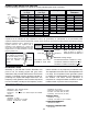
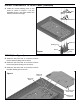
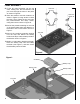
! Remove the backing from each rubber foot and
place them in the locations shown in Figure M.
! Assemble the top and bottom case sections and
fasten with four 2.8 x 8mm self-tapping screws as
shown in Figure M. Make sure the slots on the
side line up with one another.
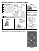
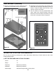
! Turn the shafts on the two potentiometers and
rotary switch fully counter-clockwise. Push the
three knobs onto the shafts so that the line on the
knobs are on the points shown in Figure N.
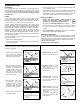
TESTING THE FG-500 FUNCTION GENERATOR
The unit may be tested by following the 4 steps listed below. Should any of these tests fail, refer to the
Troubleshooting Guide.
1) SET THE SWITCHES AND POTS AS FOLLOWS:
On/Off On
Range 10
Frequency Maximum (clockwise)
Amplitude Maximum (clockwise)
Sine/Triangle Set Sine/Triangle switch to Sine position
Figure M
2.8 x 8mm Screws
2.8 x 8mm
Screws
Rubber feet
Rubber
feet
Slot
Figure N
FINAL ASSEMBLY (continued)