
Installation Manual Gas Fires Summum 140


10
INSTALLATION MANUAL
6.4 Chimney construction for the Summum 140 4S
This instruction is intended for the Summum 140 4S and is a
supplement to the general safety requirements for installing a
gas fire, as mentioned in this manual.
Because the Summum 140 4S has glass on all sides, a separate
chimney breast must be made for both the top and bottom of
the fireplace.
Note: Depending on the chimney breast construction, the gas
connection and power supply must be taken into account.
Both must be connected under the fire. Unlike a gas fireplace
in a di erent configuration, these tubes and wires cannot be
connected from above down the chimney breast itself. The
electronics and gas control technology for this fireplace must be
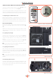
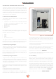
accessible at all times. So make sure that a control hatch (BDE4)
is installed (Figure I.1) or provide another service option.
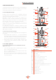
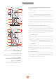
The Summum 140 4S is equipped with transport supports on
the ends of the fireplaces. For a tight alignment of the top and
bottom of the fireplace, these supports should not be removed
during installation. A er the installation is complete, the
supports can be removed and the glass side walls in front can
be replaced. The supports are secured at the top and bottom
with two screws. (Figure 6.5 through 6.8). Four glass clamps are
supplied with the fireplace, which must first be secured in place.
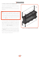
The summum 140 4S is provided with four support profiles,
which are fixed with two bolts on both long sides of the fireplace.
(see Figure 6.9) These bolts are colored red. Ensure that these
bolts are loosened before the installation is started. Loosening
the bolts ensures that the frame around the fireplace can move
in relation to the top. This prevents possible problems with the
chimney's tearing of the chimney breast!
Figure 6.5 - Rechte uitlijning van de boven en onderzijde