INSTALLATION MANUAL MODORE 185 P L E A S E L E AV E T H E S E I N ST R U CT I O N S B E H I N D W I T H T H E D E V I C E
I N STA L L AT I O N M A N UA L 2
I N STA L L AT I O N M A N UA L D O N OT US E T H I S P R O D U CT A S A P R I M A RY H E AT S O U R C E 3
I N STA L L AT I O N M A N UA L 4
I N STA L L AT I O N M A N UA L CONTENTS 1 CE STATEMENT 2 IMPORTANT SAFETY INFORMATION 3 WARRANTY 4 REMOTE CONTROL WITH FULL ELECTRONIC IGNITION 4.1 Adjusting the communication code 4.2 Igniting the pilot light 4.3 Igniting the main burner 4.4 Switching off the fireplace 5 INSTALLATION PREPARATION AND - INSTRUCTION 5.1 Relevant norms and guidelines 5.2 Attention points gas fireplace 5.3 Attention points gas connection 5.4 Requirements flue and wall terminals 5.
I N STA L L AT I O N M A N UA L 1 CE STATEMENT 2 IMPORTANT SAFETY INFORMATION We hereby declare that the design and construction of the Element4 gas appliances are complying to the essential demands and regulations for gas products. The fireplace may only be installed by a qualified installer/dealer, following these installation instructions. We advise you to read these instructions properly, before commencing the installation of your device.
I N STA L L AT I O N M A N UA L 3 WARRANTY NB: Should a problem occur, that you are not able to fix yourself with the help off the support in Appendices A to C, please contact you installer or dealer. The Element4 devices on which this warranty is applicable are made of high quality materials. Should any problem or defects still occur the following provision are in effect; For a service provision to house, outside the warranty period, the following costs ar ebeing charged: 1. • • • 2. 3.
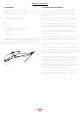
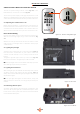
I N STA L L AT I O N M A N UA L 4 REMOTE CONTROL WITH FULL ELECTRONIC IGNITION The unit is operated using a remote control (Fig. 4.1) or the Element4 Puck, connected to a receiver (Fig. 4.2). The receiver is powered by 4 pen lite (type AA) batteries or a 6V adapter; 2 penlight batteries (type AAA) are used for the remote control. The life of the batteries is about a year with normal use. AM PM 1 2 ON OFF 4.
I N STA L L AT I O N M A N UA L 5 INSTALLATION PREPARATION AND - INSTRUCTION The device is developed, tested and approved conform the applicable standards for the usage, the performance and safety of the product. The installation of your device must apply to the current building prescriptions. We advise to make use of a qualified gas installer for the installation of your device. The installer can provide you with all information regarding the safety regulations of the installation. 5.
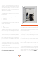
I N STA L L AT I O N M A N UA L 6 FIRE SAFE INSTALLATION To install a gas fireplace as safely as possible, several installation preparations need to be made. This overview can be used to assure the fire safety of a conversion of a fireplace. A 6.1 Fire safety device set-up B G C H D I E J M K Install the device such that there are no flammable materials around the device or chimney. The device must never be placed against a back wall of flammable materials.
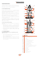
I N STA L L AT I O N M A N UA L B 6.3 Assembly regulations with flammable materials (Figure 6.3 and 6.4) G Load-bearing walls and ceilings must be covered in a protective fire resistant plate. Q L H D I E J M K Never use flammable materials around the fireplace or cove. The minimal distance between the device and non-flammable materials must be at 50 mm to ensure a convection air flow. Make sure there is a good air ventilation in the cove.
I N STA L L AT I O N M A N UA L 7 ATTENTION POINTS GAS FLUE 8 INSTALLATION CHECK AND FIRST USAGE To guarantee the fire safety regarding you flue gas configuration a casing is necessary. For this case non-combustible materials should be used. Make sure to ventilate a shaft and never to insulate it, to make sure the hot air is able to get away. 8.
I N STA L L AT I O N M A N UA L 9 ELECTRICAL CIRCUIT The app has a user friendly, interactive layout and the design is adjusted for Element4 devices. Up to eight devices can be used with one app, in the situation that multiple fire are installed in the same location. Figure 9.1 shows a simplified connection circuit for the fireplace. Every fireplace is provided with a main adapter.
I N STA L L AT I O N M A N UA L 10 MAINTENANCE INSTRUCTION This part of the manual focuses on maintenance. To ensure the optimal flame picture of your device, an annual maintenance by a competent company or installer is prescribed. 10.1 Maintenance in the combustion chamber During maintenance the glass windows of the fire need to be removed. To do this follow the following steps: 10.1.1 (Dis)assembly of the trims For a tight finish of the fireplace, trims are available.
I N STA L L AT I O N M A N UA L Figure 10.2 - Remove side trims Figure 10.5 - Put on suction cup Figure 10.3 - Remove bottom trim Figure 10.6 - Remove side glasses Figure 10.
I N STA L L AT I O N M A N UA L 11 DECORATION ARRANGEMENT Only the decoration ceramics supplied with this appliance are to be used. The ceramics must be laid only as shown on this page. Replacement parts are available from your dealer, but should only be installed by a qualified installation engineer. An elaborate decoration instruction is found on the sheet in the logset that comes with the fire. These instructions show you how to decorate the fire step by step.
I N STA L L AT I O N M A N UA L 12 USER INSTRUCTION We recommend that you have the appliance inspected annually by a recognized installer to ensure safe use and a long service life guarantee 12.1 Hand over to the customer • • • • • User manual Installation manual Instruction card decoration material Suction cups Remote control 12.2 Maintenance instructions for the installer Below is an overview of the minimum maintenance that must take place annually; • Remove the glass plate and remove all ceramic parts.
APPENDICES A FIRST AID FOR MALFUNCTION Below you will find an overview of the possible cause and solution in the event of a failure. Problem A No transmission (motor will not run) Possible Cause Solution 1 Batteries in the receiver empty Replace the batteries (4x 1.5V AA) 2 Batteries hand remote empty Replace the batteries (2x 1.
APPENDICES 4,5 mV 4,5 mV Figure A-1: Bend pin Figure A-4: Testpoint A Figure A-5: interrupter Figure A-6: Wiring receiver Figure A-3: Torx screw Figure A-7: Pilot set 40mm Figure A-2: Antenna 19
APPENDICES Problem G The pilot light goes on but goes out immediately when the main burner switches on Possible Cause Solution 1 Insufficient voltage across the thermocouple or too much resistance in the thermocouple circuit Place the measuring pins of the multimeter on the ground and black cable of the breaker. This value must be at least 4.5 mV.
APPENDICES AM PM 1 2 ON OFF Figure A.8: Second thermocouple Figure A.11: “Double plus”-button on the remote Figure A.9: Button A on “On” Figure A.13: SI-port Figure A.10: RESET-button MODE CONTACT Ignition Main Burner 1&3 High Flames 1 Pilot 3 Extinguish Main Burner Ignite second burner 1, 2 & 3 Extinguish second burner 2&3 1&2 PANEL Figure A.11: Aux-position receiver RECEIVER 3 MA GR MO SW Cable G60-ZCE/1000 2 1 Figure A.
APPENDICES B ERRORS CODES PROCONTROL APP Error code Message in App Description Possible cause F02 Contact service 5 sec beep van de ontvanger. Geen reactie van ontvanger, en geen ontsteking. • • • • F03 Contact service 5 seconds beep from the receiver. Ignition process is interrupted No response from receiver, and no ignition. Thermocouple wiring not in order / interrupted F04 Ignition failure. wait 1 minute, than try again. No pilot flame within 30 sec.
APPENDICES Error code App Message Time Description Possible Cause F04 F04 4 sec. 5 seconds beep from the receiver. No response from receiver, and no ignition. No engine end stop Wiring motor Microswitch Knob B F06 F06 4 sec. 3rd time a start attempt within 5 minutes No gas Air in the pipe No spark F09 F09 4 sec. No reaction from the fireplace.
APPENDICES C FAULTS AND ERROR CODES IN THE REMOTE This appendix can be consulted when error messages occur in the application for smartphone and tablet. C.1 F41 error This message will appear if there is no or bad Wi-Fi reception, this can be between app and router or Wi-Fi box and router By closing the App and opening it again, this is solved in most cases. Cause The cause may be that the ProControl module is blocked or is too far away from the router. See: router information.
APPENDICES D LOCATION TERMINAL D.2 Terminal location with Horizontal exhaust (C31) D.1 Terminal location with vertical exhaust (C11) Distance Position terminal dist. (mm) Directly below an opening, ventilation stone, casement window etc. 600 B Above an opening, ventilation stone, casement window etc. 300 C In addition to an opening, ventilation stone, casement window etc.
APPENDICES E GENERAL RULES FOR FLUE GAS EXTRACTION E.1 Power-Fan For flue configurations that do not function on natural draft, the PowerFan can be used. For extensive installation instructions and the operation of the PowerFan we refer to the manual of the PowerFan. E.2 Determining the flue gas extraction diameter The general rule is that you must always adhere to a flue diameter of 200/130. You always start with a vertical length of ½ meter Except : • When the stove flue pipe connection is 150/100 mm.
APPENDICES F CALCULATION TABLE FLUE GAS REDUCTION The calculation table shows when you need to place a flue gas ristrictor Result Action √ No ristrictor required R Position the resitrictor X No good operation guaranteed * F.1 Horizontal terminal flue diameter F.
APPENDICES G TECHNICAL DATA The dataplate specifies for which type of gas, gas pressure and for which country this appliance is intended. The nameplate is attached to a chain. It must remain attached to the chain. Note: Check whether the appliance is suitable for the gas type and gas pressure on site.
APPENDICES H ECODESIGN Since 1 January 2018 every fireplace has been provided with an eco-label which is always supplied with the fireplace. The ecolabel shows which category the fireplace belongs to. H.1 Ecolabels The ecolabels for the different types of gas are indicated below, respectively G20, G25 and G30.
APPENDICES I DIMENSIONAL DRAWINGS On this page and the following ones you will find dimensional drawings of the Modore 185 model and accessories with some of the important dimensions that you have to take into account when installing and installing your fireplace. Figure I.
APPENDICES I.
E L E M E N T 4 B .V. Paxtonstraat 23 8013 RP Zwolle The Netherlands Info@element4.nl www.element4fires.