
User Manual


Page 89
EA Elektro-Automatik GmbH
Helmholtzstr. 31-37 • 41747 Viersen
Germany
Fon: +49 2162 / 3785-0
Fax: +49 2162 / 16230
www.elektroautomatik.de
ea1974@elektroautomatik.de
PSB 9000 2.5 kW Series
A max. of 16 units can be connected via Share bus.
3.12.1.4 Wiring and set-up of the digital master-slave bus
Themaster-slaveconnectorsarebuilt-inandcanbeconnectedvianetworkcables(≥CAT3,patchcable).After
this,MScanbeconguredmanuallyorbyremotecontrol.Thefollowingapplies:
• A maximum of 16 units can be connected via the bus: 1 master and up to 15 slaves.
• Only devices of same kind, i.e. power supply to power supply, and of the same model, such as PSB 9080-120
to PSB 9080-120.
• Units at the end of the bus must be terminated (see below)
The master-slave bus must not be wired using crossover cables!
Later operation of the MS system implies:
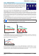
• The master unit displays, or makes available to be read by the remote controller, the sum of the actual values
of all the units
• The ranges for setting the values, adjustment limits, protections (OVP etc.) and user events (UVD etc.) of the
master are adapted to the total number of units. Thus, if e. g. 6 units each with a power of 2.5 kW are connected
together to a 15 kW system, then the master can be set in the range 0...15 kW.
• Slaves are no operable as long as being controlled by the master
• Slave units will show the alarm “MSP” in the display or by LED “Error” (where featured) as long as they not have
been initialised by the master. The same alarm is signalled after a connection drop to the master unit occurred.
• In case the function generator of the master unit is going to be used, the Share bus must be connected as well
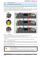
► How to connect the digital master-slave bus
1. Switchoallunitsthataretobeconnectedandconnectthemwithnetworkcables(CAT3orbetter,cables
not included). It doesn’t matter which of the two master-slave connection sockets (RJ45, backside) is con-
nected to the next unit.
2. DependingonthedesiredcongurationtheunitscanthenbeconnectedattheDCside.Thetwounitsatthe
beginning and end of the chain should be terminated, if long connection cables are used. This is achieved
using a 3-pole DIP switch which is positioned on the back side of the unit next to the MS connectors.
►
Position: not terminated (standard)
Position: fully terminated
Now the master-slave system has to be configured on each other unit. It’s recommended to configure all the slave
units first and then the master unit.
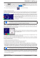
► Step 1: Configuring all slave units
1. Enter then GENERAL SETTINGS and press until reaching the master-slave settings.
2. Activate the MS mode with touch area . A warning requester will appear which has to be ac-
knowledgedwithOK,otherwisethechangewillbereverted.
3. Accept the settings with the touch area and return to the main page.
Theslaveisthenconguredformaster-slave.Repeattheprocedureforallotherslaveunits.