
User Manual


Page 55
EA Elektro-Automatik GmbH
Helmholtzstr. 31-37 • 41747 Viersen
Germany
Fon: +49 2162 / 3785-0
Fax: +49 2162 / 16230
www.elektroautomatik.de
ea1974@elektroautomatik.de
PSB 9000 2.5 kW Series
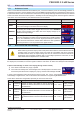
Following situations can occur:
• Remote control has been activated
During remote control via analog interface, only pin “REM-SB” determines the states of the DC terminal, according
tothelevelsdenitionsin3.6.4.4. The logical function and the default levels can be inverted by a parameter in the
setup menu of the device. See 3.5.3.1.
If the pin is unconnected or the connected contact is open, the pin will be HIGH. With param-
eter “Analog interface Rem-SB” being set to “Normal”, it requests “DC terminal on”. So when
activating remote control, the DC terminal will instantly switch on.
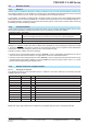
• Remote control has not been activated
In this mode of operation pin “REM-SB” can serve as lock, preventing the DC terminal from being switched on by
any means. This results in following possible situations:
DC
terminal
+
Level of
pin REM-
SB
+
Parameter
„Analog
interface
Rem-SB“
Behaviour
is o
+
HIGH
+
Normal
The DC terminal isn’t locked. It can be switched on by pushbutton
“On/O”(frontpanel)orviacommandfromdigitalinterface.
LOW
+
Inverted
+
HIGH
+
Inverted
The DC terminal is locked. It can’t be switched on by pushbutton
“On/O”(frontpanel)orviacommandfromdigitalinterface.When
trying to switch on, a pop-up in the display or an error message
will be generated.
LOW
+
Normal
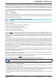
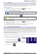
IncasetheDCterminalisalreadyswitchedon,togglingthepinwillswitchtheDCterminalo,similartowhatit
does in analog remote control:
DC
terminal
+
Level of
pin REM-
SB
+
Parameter
„Analog
interface
Rem-SB“
Behaviour
is on
+
HIGH
+
Normal
The DC terminal remains on, nothing is locked. It can be switched
onorobypushbuttonordigitalcommand.
LOW
+
Inverted
+
HIGH
+
Inverted
TheDCterminalwillbeswitchedoandlocked.Lateritcanbe
switched on again by toggling the pin. During lock, pushbutton
or digital command can delete the request to switch on by pin.
LOW
+
Normal
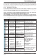
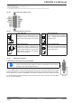
b) Remote control of current and power (source mode)
Requires remote control to be activated (Pin REMOTE = LOW)
The set values PSEL and CSEL are generated from, for example, the
reference voltage VREF, using potentiometers for each. Hence the
power supply can selectively work in current limiting or power limit-
ingmode.Accordingtothespecicationofmax.5mAfortheVREF
output,potentiometersofatleast10kΩmustbeused.
The voltage set value VSEL is directly connected to VREF and will
thus be permanently 100%. This also means that the device can only
work in source mode.
If the control voltage is fed in from an external source it’s necessary to
consider the input voltage ranges for set values (0...5 V oder 0...10 V).
Use of the input voltage range 0...5 V for 0...100%
set value halves the eective resolution.
Example with external
voltage source
Example with
potentiometers