EasyPS2000 Software User‘s Guide Technical requirements • PC with at least 2GHz, 2GB RAM, USB port(s) with USB1.1 or higher • Windows XP OS or newer • Power supply unit PS 2000 B • Unrestricted Windows user permissions • EasyPS2000 software version 2.
Table of contents 1. Preamble............................................................................................................................ 32 2. Driver installation............................................................................................................... 32 2.1 Trouble-shooting driver installation problems............................................................... 33 3. EasyPS2000 software installation...................................................................
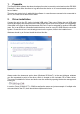
1. Preamble The EasyPS2000 software has been developed in order to remotely control and monitor PS 2000 B devices. It also offers functions to log data from the device or to run automated sequences in form of tables. The user can control only 1 unit with the software. In case there are several units connected to the PC, the user has to select one of them. 2. Driver installation Connect the unit to the PC via the included USB cable.
2.1 Trouble-shooting driver installation problems When connecting a new device to the PC and if the driver is not already installed on the system, Windows should ask for a driver. In case it does not, the failed driver installation is reported by Windows.
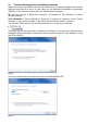
Windows will then install the device. After a successful installation the device can be found as „PS2000 Single“ in the device manager, in section „Ports (COM & LPT)“. Note: The COM port number 8 above is only an example. Windows assigns a new COM port for every new device of this type that is installed in the system. The port is remembered and used again if the device is connected the next time.
4. Introduction 4.1 Start After a successful installation and a restart of the PC, the software can be started from the Windows start menu in Start à All Programs à EasySoft à EasyPS2000.
Once the scan is finished, one of the following results may appear: • No PS 2000 B detected Figure 7 In case no unit was detected, please check if the PS2000 unit is properly connected to the PC (USB cable plugged correctly), if the driver is installed completely and if the device is listed in the device manager: Windows XP: Start (or desktop) Right-click „Computer“ Properties Tab „Hardware“ Button „Device manager“ Windows Vista / Windows 7: Start (or desktop) à Right-click „Computer“ à Propertie
• One PS 2000 B detected (not licensed) Figure 8 Note: if only one unit PS 2000 B is connected and the unit is already unlocked for the software, i.e. status is licensed, this screen is skipped automatically. Otherwise, when showing status „Not licensed“, the device has to be unlocked once by a license code which can be purchased as an option. See section „4.3 Entering the license code“.
• Multiple PS 2000 B detected Figure 9 If multiple units have been detected (two in the example above), the user has to select one of them by clicking the corresponding row and confirming the selection with the SUBMIT button. As long as the selected device is not licensed yet, submitting it will open the licensing dialogue first. In this dialogue you can enter the license code which belongs to the particular device and unlock the unit in the software.
4.2 How to purchase a license code A license code can be purchased seperately and upon request to the local distributor or hardware manufacturer and only requires to report the device‘s serial number (by mail or phone). The serial can be either found on the type plate on the rear of the device or in the device information window in EasyPS2000. In order to show the device information of a device you can use the list of detected devices that is shown after a scan (figure 10).
4.4 Selecting a view mode You can select from three different control GUI views: Select those views from the menu „View“. The views Standard and Compact show a graphical user interface, which corresponds to the front view of the device. The control elements (buttons, knobs) have the same function as the ones on the device. The little USB plug, depicted on the position of the USB socket, can additionally be used to switch between manual and remote control of the device.
• Compact view Figure 13 View mode „Compact“ is completely for use with the mouse, like when manually operating the device. Changeover between manual and remote control is here done on the small USB plug graphic. • Extended view Figure 14 View mode „Extended“ shows all values and the device status as text and numbers.
4.5 The menu • View Selects between different views of the GUI. Also see „4.4 Selecting a view mode“. • Device Menu item Device has two subitems: ▪▪ Information Opens a window that shows device related information of the currently controlled or selected device. ▪▪ Scan Scans for connected PS 2000 B units and lists them, as long as multiple units have been detected or if the only connected unit is not licensed. Also see „4.1 Start“.
4.6 Options Menu item „Options“ is used to do settings for the application, the data logging, the sequencing and the visualisation (graph). • Logging options Settings for data logging feature. For PS 2000 B models with two main outputs, logging is seperate for each output. Figure 15 ▪▪ Log file path Button New opens a „Save as...“ dialogue in order to create a new log file. The log file is then used to write log data.
▪▪ Log interval Defines the interval to write log data into the log file. Minimum: 0.5s Step width: 0.5s Default setting: 0.5s The log interval input box uses the time format 00:00:00,0, which means HH:MM:SS,MS. If entering, for example, 00:00:00,5 this will result in 0.5s log interval or with 00:10 it will be 10 minutes or if just entering 1 it will be 1 hour. ▪▪ Start logging automatically with sequencing Defines, if data logging is automatically started together with the start of sequencing.
• Sequencing options Figure 16 ▪▪ Sequence file path Shows the path of the selected sequence file or selects a sequence file with the folder button to the right. ▪▪ Sequence file name Shows the name of the selected sequence file. ▪▪ Sequencing with repetition Defines, if and how often a sequence is repeated. Default settings: deactivated, 1.
• Application Figure 17 ▪▪ Application log file path Defines and shows the path where the application stores its application log file (type CSV), in case the feature is activated with „Save application log“ in the options. ▪▪ Application log file name Only shows the name of the application log file. ▪▪ View Application log file Opens the application log file, which has been defined in the options, in the assigned application for viewing (eg. Excel or OpenOffice Calc).
• Graph options Settings for graph window. Depending on the device model, i.e. single or triple output, seperate settings for the main outputs are possible here. Figure 18 ▪▪ Time Range Selects the default time range of the graph‘s X axis. The graph window or windows can be opened using the corresponding submenu item in menu „Action“. The time range setting can be changed in the graph windows too, while the graph is stopped, but there the selection is only temporary.
5. Operation and handling 5.1 Sequencing and logging Sequencing is the step by step processing of a value table, which can control the device almost automatedly. Those tables can be created in MS Excel or OpenOffice Calc or similar, saved as so-called CSV files (seperator: semicolon) and loaded in EasyPS2000. The rows of the table define conditions, which the device shall set for a certain time. The setup of the table is defined as explained below.
The „actual log row“ has only informative character. Note: depending on the adjustable log interval, logged values will have a certain skew to the values that are displayed on the device or to those which can be measured at the device‘s output. Example: the device is dynamically loaded with different currents and by logging the current progression shall be recorded. At time x the device had the actual current of 2.52A, which was increased to 3A only 30ms later.
5.1.2 Details about the sequence file for single output models (Single) In order to run sequencing, a sequence file has to be selected in tab „Sequencing“ of the options dialogue. Otherwise, sequencing is not accessible. Following is required for Sequencing: • The device is already in remote control mode • The sequence file is correct and accepted by the application The required format of the sequence file is defined like this: The first row is only a header, captioning the columns.
Minute - Together with columns F, H und I, it defines the time for the actual row in format H:M:S,MS. That time has to elapse until the next row is processed. Allowed value range: 0…59 (integers only) Second - Together with columns F, G und I, it defines the time for the actual row in format H:M:S,MS. That time has to elapse until the next row is processed.
5.2 Visualisation 5.2.1 Introduction Visualisation (or: the graph) is a graphical display of set values and actual values in a temporal progression. The displayed time period (X axis) can be varied between 1 second and 10 minutes in 4 steps, as long as the graph is stopped. The window „Visualisation“ can be accessed via the menu „Actions“ à „Graph“ resp. „Graph output 1“ or „Graph output 2“.
5.2.2 Other functions History The graph records up to four plots over time. The recorded data is available in a history, which can be accessed after the graph is stopped. The scrollbar below the X axis can be used to select a section of the recorded history between 0 and end. Sections can be zoomed or saved as image. See below. Screenshots It is possible to save screenshots from the graph‘s history.
Signal menu By clicking on the black rectangles next to the signal name, the signal‘s appearance can be changed like line thickness, line type, color etc. Note: screenshot taken from german context. Diagram type Colour Line type Line thickness Anti-Aliasing Bar plots Fill baseline Dotted display X axis Y axis These settings are mostly self-explaining.
5.3 The application log The application can record a log about events like actions done or errors. By default, this feature is deactivated. In order to activate it, access the options in tab „Application“. See section 4.6 and fFigure 17 on page 46. To have a view into the log, go to menu „Help“ and select „View application log file“: The application log file is called ps2_application_steps.csv by default. But you choose a different name in the options dialogue in tab „Application“.
6. Firmware update A firmware1 update is normally done to implement new or altered feature to your device or to remove bugs. In order to update the firmware of your PS 2000 B, access menu item „Update device“ in menu „Help“. A dialogue will guide you through the update process. Before you can update your device, you need to have a new firmware file, which can either be found on the website of the device manufacturer or the website of your local distributor or upon request. 7.
Problem: In „Standard“ view it does not show the lower control elements anymore Solution(s): Exit the application, open Windows Explorer and go to the installation folder of EasyPS2000, change to subfolder \data and delete the file „ps2000.ini“ and restart the application. Attention! This will reset all settings in the options window to defaults Note: Avoid resizing the main window on the window edge. Maximising is allowed and done with the typical Windows maximise button.