
User Manual

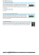
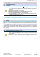
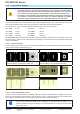
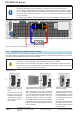
Table Of Contents
- 06230350_DE
- 1. Allgemeines
- 1.1 Zu diesem Dokument
- 1.2 Symbolerläuterungen
- 1.3 Gewährleistung und Garantie
- 1.4 Haftungsbeschränkungen
- 1.5 Entsorgung des Gerätes
- 1.6 Produktschlüssel
- 1.7 Bestimmungsgemäße Verwendung
- 1.8 Sicherheit
- 1.9 Technische Daten
- 1.10 Aufbau und Funktion
- 1.10.1 Allgemeine Beschreibung
- 1.10.2 Blockdiagramm
- 1.10.3 Lieferumfang
- 1.10.4 Zubehör
- 1.10.5 Optionen
- 1.10.6 Die Bedieneinheit (HMI)
- 1.10.7 USB-Port Typ B (Rückseite)
- 1.10.8 Steckplatz für Schnittstellenmodule
- 1.10.9 Analogschnittstelle
- 1.10.10 Share-Bus-Anschluß
- 1.10.11 Sense-Anschluß (Fernfühlung)
- 1.10.12 Master-Slave-Bus
- 2. Installation & Inbetriebnahme
- 2.1 Transport und Lagerung
- 2.2 Auspacken und Sichtkontrolle
- 2.3 Installation
- 2.3.1 Sicherheitsmaßnahmen vor Installation und Gebrauch
- 2.3.2 Vorbereitung
- 2.3.3 Aufstellung des Gerätes
- 2.3.4 Anschluß an das Stromnetz (AC)
- 2.3.5 Anschluß von DC-Lasten
- 2.3.6 Erdung des DC-Ausgangs
- 2.3.7 Anschluß der Fernfühlung
- 2.3.8 Installation eines AnyBus-Schnittstellenmoduls
- 2.3.9 Anschluß der analogen Schnittstelle
- 2.3.10 Anschließen des „Share-Bus“
- 2.3.11 Anschluß des USB-Ports (Rückseite)
- 2.3.12 Erstinbetriebnahme
- 2.3.13 Erneute Inbetriebnahme nach Firmwareupdates bzw. längerer Nichtbenutzung
- 3. Bedienung und Verwendung
- 3.1 Personenschutz
- 3.2 Regelungsarten
- 3.3 Manuelle Bedienung
- 3.4 Fernsteuerung
- 3.5 Alarme und Überwachung
- 3.6 Bedieneinheit (HMI) sperren
- 3.7 Nutzerprofile laden und speichern
- 3.8 Der Funktionsgenerator
- 3.8.1 Einleitung
- 3.8.2 Allgemeines
- 3.8.3 Arbeitsweise
- 3.8.4 Manuelle Bedienung
- 3.8.5 Sinus-Funktion
- 3.8.6 Dreieck-Funktion
- 3.8.7 Rechteck-Funktion
- 3.8.8 Trapez-Funktion
- 3.8.9 DIN 40839-Funktion
- 3.8.10 Arbiträr-Funktion
- 3.8.11 Rampen-Funktion
- 3.8.12 UI- und IU-Tabellenfunktion (XY-Tabelle)
- 3.8.13 PV-Tabellenfunktion (Photovoltaik)
- 3.8.14 FC-Tabellenfunktion (Brennstoffzelle)
- 3.8.15 Fernsteuerung des Funktionsgenerators
- 3.9 Weitere Anwendungen
- 4. Instandhaltung & Wartung
- 5. Zubehör und Optionen
- 6. Service & Support
- 1. Allgemeines
- 06230350_EN
- 1. General
- 1.1 About this document
- 1.2 Explanation of symbols
- 1.3 Warranty
- 1.4 Limitation of liability
- 1.5 Disposal of equipment
- 1.6 Product key
- 1.7 Intended usage
- 1.8 Safety
- 1.9 Technical Data
- 1.10 Construction and function
- 1.10.1 General description
- 1.10.2 Block diagram
- 1.10.3 Scope of delivery
- 1.10.4 Accessories
- 1.10.5 Options
- 1.10.6 The control panel (HMI)
- 1.10.7 USB port type B (rear side)
- 1.10.8 Interface module slot
- 1.10.9 Analog interface
- 1.10.10 Share Bus-Connection
- 1.10.11 Sense connector (remote sensing)
- 1.10.12 Master-Slave bus
- 2. Installation & commissioning
- 2.1 Transport and storage
- 2.2 Unpacking and visual check
- 2.3 Installation
- 2.3.1 Safety procedures before installation and use
- 2.3.2 Preparation
- 2.3.3 Installing the device
- 2.3.4 Connection to AC supply
- 2.3.5 Connection to DC loads
- 2.3.6 Grounding of the DC output
- 2.3.7 Connecting the “Share” bus
- 2.3.8 Connection of remote sense
- 2.3.9 Installation of an AnyBus interface module
- 2.3.10 Connecting the analog interface
- 2.3.11 Connecting the USB port (rear side)
- 2.3.12 Initial commission
- 2.3.13 Commission after a firmware update or a long period of non-use
- 3. Operation and application
- 3.1 Personal safety
- 3.2 Operating modes
- 3.3 Manual operation
- 3.4 Remote control
- 3.5 Alarms and monitoring
- 3.6 Control panel (HMI) lock
- 3.7 Loading and saving a user profile
- 3.8 The function generator
- 3.8.1 Introduction
- 3.8.2 General
- 3.8.3 Method of operation
- 3.8.4 Manual operation
- 3.8.5 Sine wave function
- 3.8.6 Triangular function
- 3.8.7 Rectangular function
- 3.8.8 Trapezoidal function
- 3.8.9 DIN 40839 function
- 3.8.10 Arbitrary function
- 3.8.11 Ramp Function
- 3.8.12 UI and IU table functions (XY table)
- 3.8.13 PV table function (photovoltaics)
- 3.8.14 FC table function (fuel cell)
- 3.8.15 Remote control of the function generator
- 3.9 Other applications
- 4. Service and maintenance
- 5. Accessories and options
- 6. Service & Support
- 1. General
Page 28
PSI 9000 3U Series
www.elektroautomatik.de
ea1974@elektroautomatik.de
EA Elektro-Automatik GmbH
Helmholtzstr. 31-33 • 41747 Viersen
Germany
Fon: +49 2162 / 3785-0
Fax: +49 2162 / 16230
1.10.10 Share Bus-Connection
The 2 pole WAGO socket (“Share”) on the back side of the device is provided for
connection to equally named sockets on compatible power supplies series to achieve
a balanced load current distribution during parallel connection. The socket is also
used to connect the power supply to compatible electronic loads, in order to build a
two-quadrants operation setup. Following power supply and electronic load series
are compatible:
• PS 9000 2U/3U (new from 2014)
• PSI 9000 2U/3U (new from 2014)
• ELR 9000
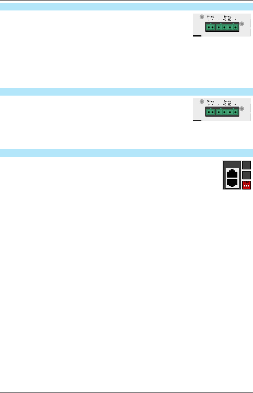
1.10.11 Sense connector (remote sensing)
If the output voltage has to be dependant on the consumer location rather than the DC
output of the power supply, then the input “Sense” can be connected to the consumer
where the DC connection is made. This compensates, up to a certain limit, the volt-
age difference between the power supply output and the consumer, which is caused
by the high current through the load cables. The maximum possible compensation
is given in the technical data.
1.10.12 Master-Slave bus
A further port is provided on the back side of the device, comprising two RJ45 sockets, which
enables multiple identical devices to be connected via a digital bus (RS485) to create a master-
slave system. Connection is made using standard CAT5 cables. These can theoretically have
a length of up to 1200 m, but it is recommended to keep the connections as short as possible.