
User Manual


Page 61
EA Elektro-Automatik GmbH
Helmholtzstr. 31-33 • 41747 Viersen
Germany
Fon: +49 2162 / 3785-0
Fax: +49 2162 / 16230
www.elektroautomatik.de
ea1974@elektroautomatik.de
PSI 9000 2U Series
3.8 The function generator
3.8.1 Introduction
The built-in function generator is, like the equally named electronic devices, able to create various signal forms
and apply these to set values for voltage or current.
Whilst R mode is activated, access to the function generator is not available.
The generator functions can be manually operated completely on the device. In remote control, only the customis-
ablearbitrarygeneratorandaXYfunctionareavailable,whichcanbeconguredandcontrolledviadigitalcom-
munication. The arbitrary generator can replicate all manually serviceable functions, except UI and IU For UI/IU,
the XY function is assigned.
Thefollowingfunctionsareretrievable,congurableandcontrollable:
Function Usable
on
Short description
Sine wave U, I Sine wave generation with adjustable amplitude, offset and frequency
Triangle U, I Triangular wave signal generation with adjustable amplitude, offset, gain and decay times
Rectangular U, I Rectangular wave signal generation with adjustable amplitude, offset and duty cycle
Trapezoid U, I Trapezoidal wave signal generation with adjustable amplitude, offset, rise time, pulse
time, fall time, idle time
DIN 40839 - Simulated automobile engine start curve according to DIN 40839 / EN ISO 7637, split
into5curvesequences,eachwithastartvoltage,nalvoltageandtime
Arbitrary U, I Generationofaprocesswithupto100freelycongurablesteps,eachwithastartand
end value (AC/DC), start and end frequency, phase angle and total duration
Ramp U, I Generation of a linear rise or fall ramp with start and end values and time before and
after the ramp
UI-IU - Table(.csv)withvaluesforUorI,uploadedfromaUSBashdrive
3.8.2 General
3.8.2.1 Limitations
The function generator is not accessible, neither for manual acces, nor for remote control, if
• master-slavemodehasbeenactivatedandthedevicewasconguredasslave.
• resistance modes (R/I adjustment mode, also called UIR mode) is active.
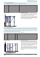
3.8.2.2 Resolution of X (Time) and Y (Amplitude)
The device can set 4096 steps between 0 ... 100% of nominal value. The intervals to create a linear or other rise/
fall are calculated depending on the amplitude and then set.
If the amplitude is very low and the time long, only few intervals will be set as otherwise many identical values will
be set one after another, generating a staircase effect.
3.8.2.3 Possible technical complications
Operation of switching mode power supplies as a voltage source can, when applying a function to the output volt-
age, lead to damage of the output capacitors due to continuous charging/discharging which causes overheating.
Furthermoretheactualvoltageprogressionmaydifferfromwhat’sexpected.
3.8.3 Method of operation
In order to understand how the function generator works and how the value settings interact, the following should
be noted:
The device operates, including in function generator mode,always with the three set values U,I and P.
The selected function can be used on one of both the values U or I, the other two are then constants and have
a limiting effect. That means if, for example, a voltage of 10 V is set for the DC output, a load is connected and
a sine wave function should operate on the current with an amplitude of 20 A and offset 20 A, then the function
generator will create a sine wave progression of current between 0 A (min) and 40 A (max), which will result in an
output power between 0 W (min) and 400 W (max).The output power, however, is limited to its set value. If this
were 300 W then, in this case, the current would be limited to 30 A and, if clamped to an oscilloscope, it would be
seen to be capped at 30 A and never achieve the target of 40 A.