
User Manual
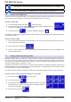
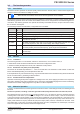
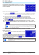
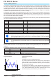
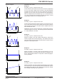
Table Of Contents
- 06230350_DE
- 1. Allgemeines
- 1.1 Zu diesem Dokument
- 1.2 Symbolerläuterungen
- 1.3 Gewährleistung und Garantie
- 1.4 Haftungsbeschränkungen
- 1.5 Entsorgung des Gerätes
- 1.6 Produktschlüssel
- 1.7 Bestimmungsgemäße Verwendung
- 1.8 Sicherheit
- 1.9 Technische Daten
- 1.10 Aufbau und Funktion
- 1.10.1 Allgemeine Beschreibung
- 1.10.2 Blockdiagramm
- 1.10.3 Lieferumfang
- 1.10.4 Zubehör
- 1.10.5 Optionen
- 1.10.6 Die Bedieneinheit (HMI)
- 1.10.7 USB-Port Typ B (Rückseite)
- 1.10.8 Steckplatz für Schnittstellenmodule
- 1.10.9 Analogschnittstelle
- 1.10.10 Share-Bus-Anschluß
- 1.10.11 Sense-Anschluß (Fernfühlung)
- 1.10.12 Master-Slave-Bus
- 2. Installation & Inbetriebnahme
- 2.1 Transport und Lagerung
- 2.2 Auspacken und Sichtkontrolle
- 2.3 Installation
- 2.3.1 Sicherheitsmaßnahmen vor Installation und Gebrauch
- 2.3.2 Vorbereitung
- 2.3.3 Aufstellung des Gerätes
- 2.3.4 Anschluß an das Stromnetz (AC)
- 2.3.5 Anschluß von DC-Lasten
- 2.3.6 Erdung des DC-Ausgangs
- 2.3.7 Anschluß der Fernfühlung
- 2.3.8 Installation eines AnyBus-Schnittstellenmoduls
- 2.3.9 Anschluß der analogen Schnittstelle
- 2.3.10 Anschließen des „Share-Bus“
- 2.3.11 Anschluß des USB-Ports (Rückseite)
- 2.3.12 Erstinbetriebnahme
- 2.3.13 Erneute Inbetriebnahme nach Firmwareupdates bzw. längerer Nichtbenutzung
- 3. Bedienung und Verwendung
- 3.1 Personenschutz
- 3.2 Regelungsarten
- 3.3 Manuelle Bedienung
- 3.4 Fernsteuerung
- 3.5 Alarme und Überwachung
- 3.6 Bedieneinheit (HMI) sperren
- 3.7 Nutzerprofile laden und speichern
- 3.8 Der Funktionsgenerator
- 3.8.1 Einleitung
- 3.8.2 Allgemeines
- 3.8.3 Arbeitsweise
- 3.8.4 Manuelle Bedienung
- 3.8.5 Sinus-Funktion
- 3.8.6 Dreieck-Funktion
- 3.8.7 Rechteck-Funktion
- 3.8.8 Trapez-Funktion
- 3.8.9 DIN 40839-Funktion
- 3.8.10 Arbiträr-Funktion
- 3.8.11 Rampen-Funktion
- 3.8.12 UI- und IU-Tabellenfunktion (XY-Tabelle)
- 3.8.13 PV-Tabellenfunktion (Photovoltaik)
- 3.8.14 FC-Tabellenfunktion (Brennstoffzelle)
- 3.8.15 Fernsteuerung des Funktionsgenerators
- 3.9 Weitere Anwendungen
- 4. Instandhaltung & Wartung
- 5. Zubehör und Optionen
- 6. Service & Support
- 1. Allgemeines
- 06230350_EN
- 1. General
- 1.1 About this document
- 1.2 Explanation of symbols
- 1.3 Warranty
- 1.4 Limitation of liability
- 1.5 Disposal of equipment
- 1.6 Product key
- 1.7 Intended usage
- 1.8 Safety
- 1.9 Technical Data
- 1.10 Construction and function
- 1.10.1 General description
- 1.10.2 Block diagram
- 1.10.3 Scope of delivery
- 1.10.4 Accessories
- 1.10.5 Options
- 1.10.6 The control panel (HMI)
- 1.10.7 USB port type B (rear side)
- 1.10.8 Interface module slot
- 1.10.9 Analog interface
- 1.10.10 Share Bus-Connection
- 1.10.11 Sense connector (remote sensing)
- 1.10.12 Master-Slave bus
- 2. Installation & commissioning
- 2.1 Transport and storage
- 2.2 Unpacking and visual check
- 2.3 Installation
- 2.3.1 Safety procedures before installation and use
- 2.3.2 Preparation
- 2.3.3 Installing the device
- 2.3.4 Connection to AC supply
- 2.3.5 Connection to DC loads
- 2.3.6 Grounding of the DC output
- 2.3.7 Connecting the “Share” bus
- 2.3.8 Connection of remote sense
- 2.3.9 Installation of an AnyBus interface module
- 2.3.10 Connecting the analog interface
- 2.3.11 Connecting the USB port (rear side)
- 2.3.12 Initial commission
- 2.3.13 Commission after a firmware update or a long period of non-use
- 3. Operation and application
- 3.1 Personal safety
- 3.2 Operating modes
- 3.3 Manual operation
- 3.4 Remote control
- 3.5 Alarms and monitoring
- 3.6 Control panel (HMI) lock
- 3.7 Loading and saving a user profile
- 3.8 The function generator
- 3.8.1 Introduction
- 3.8.2 General
- 3.8.3 Method of operation
- 3.8.4 Manual operation
- 3.8.5 Sine wave function
- 3.8.6 Triangular function
- 3.8.7 Rectangular function
- 3.8.8 Trapezoidal function
- 3.8.9 DIN 40839 function
- 3.8.10 Arbitrary function
- 3.8.11 Ramp Function
- 3.8.12 UI and IU table functions (XY table)
- 3.8.13 PV table function (photovoltaics)
- 3.8.14 FC table function (fuel cell)
- 3.8.15 Remote control of the function generator
- 3.9 Other applications
- 4. Service and maintenance
- 5. Accessories and options
- 6. Service & Support
- 1. General
Page 56
PSI 9000 3U Series
www.elektroautomatik.de
ea1974@elektroautomatik.de
EA Elektro-Automatik GmbH
Helmholtzstr. 31-33 • 41747 Viersen
Germany
Fon: +49 2162 / 3785-0
Fax: +49 2162 / 16230
User events are an integral part of the actual user prole. Thus, if another user prole, or the
default prole, is selected and used, the events will be either differently or not congured.
The set values can be entered using the ten-key tab. This will appear by tapping the touch area
on the particular page, e.g. “4.1 Event U”, showing the rotary knob assignments.
3.6 Control panel (HMI) lock
In order to avoid the accidental alteration of a value during manual operation the rotary knobs or the touchscreen
can be locked so that no alteration of values will be accepted without prior unlocking.
► How to lock the HMI
1. In the main page, tap the lock symbol (upper right corner).
2. In the settings page you can select between the complete HMI (“Lock all”) lock or
except for the On/Off button (“ON/OFF possible”)
3. Activate the lock with . The status “Locked” is displayed as .
If an attempt is made to alter something whilst the HMI is locked, a requester appears in the display asking if the
lock should be disabled.
► How to unlock the HMI
1. Tap any part of the touchscreen of the locked HMI, or turn one of the rotary knobs or press the button “On/
Off” (in complete lock situation).
2. This request pop-up will appear: .
3. Unlock the HMI by tapping on “Tap to unlock” within 5 seconds, otherwise the pop-up will disappear and
the HMI remains locked.
3.7 Loading and saving a user prole
The menu “Proles”servestoselectbetweenadefaultproleandupto5userproles.Aproleisacollectionof
allsettingsandsetvalues.Upondelivery,orafterareset,all6proleshavethesamesettingsandallsetvalues
are0.Iftheuserchangessettingsorsetstargetvaluesthenthesecreateaworkingprolewhichcanbesavedto
oneofthe5userproles.Theseprolesorthedefaultonecanthenbeswitched.Thedefaultproleisread-only.
Loadingthedefaultproleisequivalenttoareset.
Thepurposeofaproleistoloadasetofsetvalues,settingslimitsandmonitoringthresholdsquicklywithout
havingtoreadjustthese.AsallHMIsettingsaresavedintheprole,includinglanguage,aprolechangecanalso
be accompanied by a change in HMI language.
Oncallingupthemenupageandselectingaprolethemostimportantsettingscanbeseen,butnotchanged.
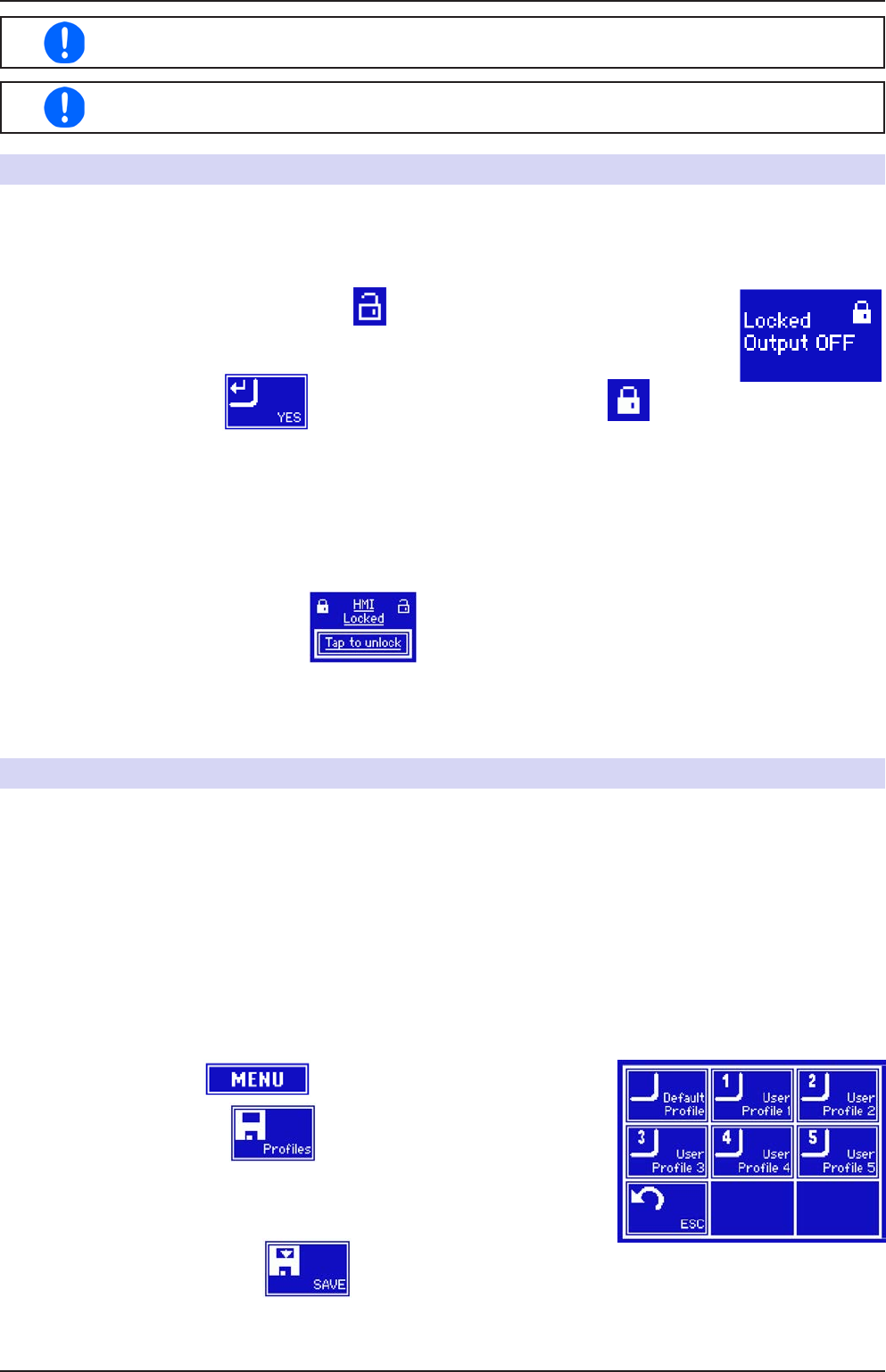
► How to save the current values and settings as a user prole:
1. Tap the touch area on the main screen
2. In the menu page, tap .
3. Intheselectionscreen(right)choosebetweenuserprole1-5inwhich
thesettingsaretobesaved.Theprolewillthenbedisplayedandthe
values can be checked, but not changed.
4. Save using the touch area