
User Manual


74
© 2006, Elektro-Automatik GmbH & Co. KG
Irrtümer und Änderungen vorbehalten
EN
Instruction Manual
PSI 8000 3U Series
Date: 03-22-2011
11. Miscellaneous
11.1 Parallel connection in Share bus mode
Share bus operation is used to gain a symmetric load current
distribution when running multiple units in parallel connection.
Important: in this operation mode, the unit with the highest output
voltage controls and denes the output voltage of the whole
parallel connection. It means, any unit of the system could be
in charge. Thus it recommended to pick a unit that is used to
control the whole system, while the set value of voltage for the
remaining units is set to the required minimum. Voltage and po-
wer set value could be set to 100% or, if not desired, set to equal
values on every unit so that the total results in what‘s required.
In case a unit is broken and will completely shut off, the parallel
connection will continue to work without interruption. This is
called redundancy.
For a device error like overtemperature (OT) or overvoltage,
the output voltage will rise or fall to the highest value that was
adjusted on any of the remaining units.
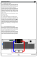
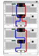
The wiring of terminal „Share“, which is required for Share bus
operation, is explained in section „5.8. Terminal „Share““. Also
see gure 13 below.
Note: if remote sense is going to be used, it is recommended
only to connect the „Sense“ input of the main unit that deter-
mines the system voltage.
Attention! This is a purely analogue connection. No totals
formation of actual values on any of the units.
11.2 Series connection
Series connection of two or more units is generally allowed.
But there are some restrictions and rules to consider because
of safety and isolation reasons:
• No negative DC output pole of a unit in the series
connection may be raised to a potential >300V against
ground (PE)!
• Every unit is adjusted seperately, there is no master-slave
connection.
• The Share bus must not be wired!
• The grounds (AGND, DGND) of the analogue interfaces
of the units in series connection must not be wired to
each other!
• Remote sense must not be wired!
• It is recommended to build a series connection only with unit
of same model.
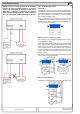
Example: Three identical units with 200V nominal voltage, for
example PSI 8200-70 3U, shall be connected in series. When
calculating, the total voltage of that series connection could go
up to 600V. Looking at the resulting potentials on the negative
outputs of the units, the 3rd unit negative DC pole could be
raised to 400V if all units put out maximum voltage. This is
not permitted! So one of the lower units has to be limited to a
certain maximum. The gure below claries that the resulting
total voltage would only be 500V:
Operating the device
11.3 Accessories and options
Following accessories are optionally available:
a) Digital interface cards
Pluggable and retrotable, digital interface cards for USB,
RS232, CAN, GPIB/IEEE (SCPI only), Ethernet/LAN (SCPI
only) or Probus are available. There is one interface card slot
available with every device model.
b) Analogue interface card
Pluggable and retrotable, galvanically isolated, 25 pole ana-
logue card. For details refer to the seperate interface cards
instruction manual.
Following options are available:
a) High Speed Ramping
Increased dynamics of the output voltage by reduced output
capacity. It must be pointed out, that other output related values
also increase!
Note: this is a permanent modication which is not switchable.
b) Watercooling
Internally integrated water cooling block. The watercooling is
used prevent premature shutdown of the power output because
of overheating.
c) Internal resistance regulation
This option can be purchased subsequently and is unlocked
with a code number in the device‘s setup menu.
After it is unlocked, the user can choose between U/I/P or U/I/R
operation. The power set value will not be adjustable in U/I/R
mode, it is then only dened as a limit in the device settings.
Note: it will eventually be required to update the device rmware
before the option can be unlocked. Ask your supplier.
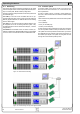
11.4 Firmware update
A rmware update of the device should only be done if the
device shows erroneous behaviour or if new features have
been implemented.
In order to update a device, it requires a certain digital inter-
face card, a new rmware le and a Windows software called
„Update tool“.
These interfaces are qualied to be used for a rmware update:
• IF-U1 (USB)
• IF-R1 (RS232)
• IF-E1 (Ethernet/USB)
• IF-PB1 (Probus/USB)
In case none of the above interface types is at hand, the device
can not be updated. Please contact your dealer for a solution.
The update tool and the particular rmware le for your device
are obtainable from the website of the device manufacturer, or
are mailed upod request. The update too will guide the user
through the semi-automatic update process.